Engines Iveco N45, N67. Manual — part 16
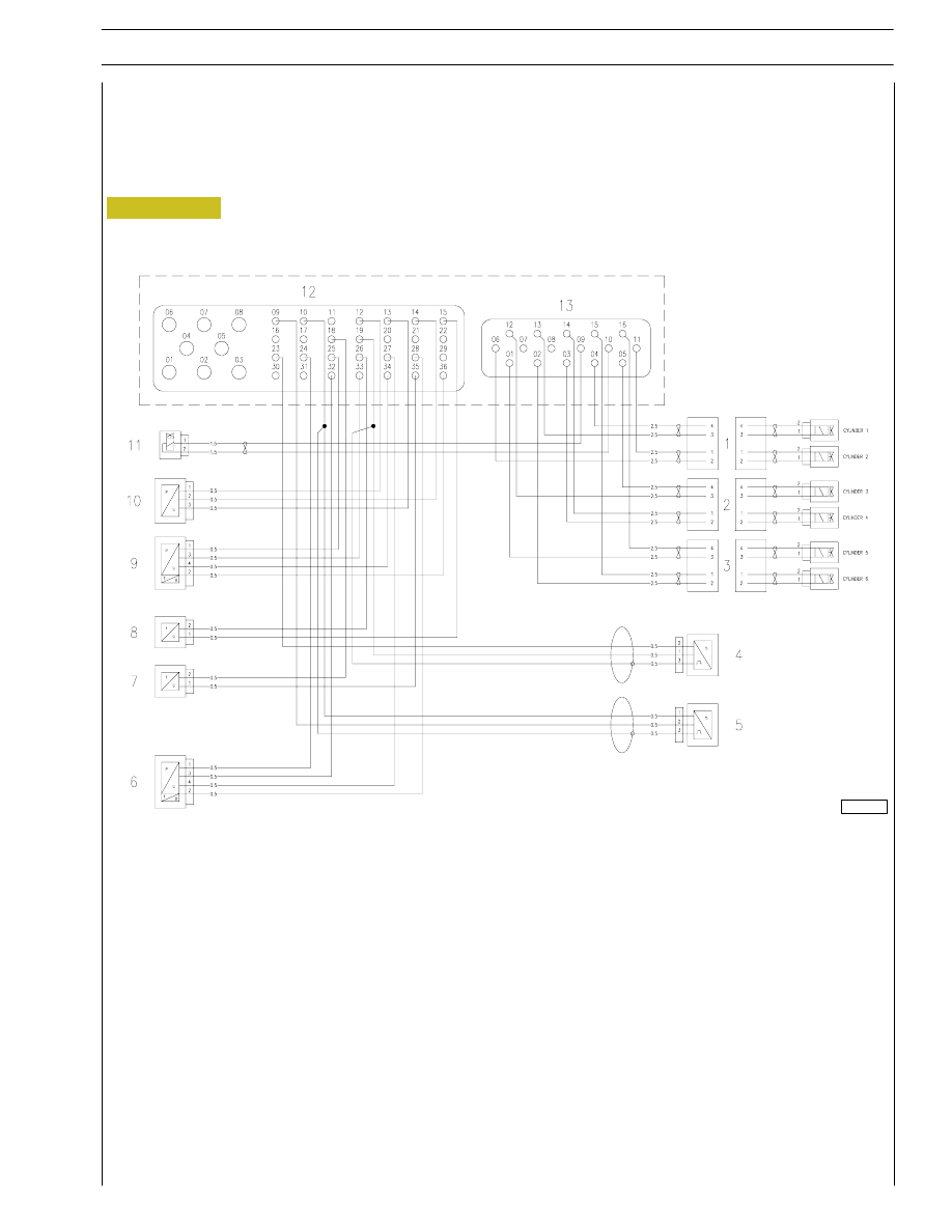
Figure 98
1. Injectors for cylinders 1-2 - 2 Injectors for cylinders 3-4 - 3. Injectors for cylinders 5-6 - 4. Engine rpm sensor -
5. Timing sensor - 6. Engine oil pressure and temperature sensor - 7. Fuel temperature sensor -
8. Coolant temperature sensor - 9. Air temperature and pressure sensor - 10. Rail temperature and pressure sensor -
11. Pressure regulator - 12. Connector C EDC control unit (signal) - 13. Connector A EDC control unit (power).
Cable on engine
All the components described below refer to the engine cable in question, therefore the connections to the pins are a preliminary
version, in other words at the approval stage.
0051064t
SECTION 3 - DUTY-INDUSTRIAL APPLICATION
35
F4HE NEF ENGINES
Print P2D32N003GB
Base - February 2006

Injectors connector (A)
Sensors connector (C)
36
SECTION 3 - DUTY-INDUSTRIAL APPLICATION
F4HE NEF ENGINES
Base - February 2006
Print P2D32N00GB
ECU PIN
FUNCTION
ECU PIN
ECU PIN
1
Cylinder 5 injector
1
-
2
Cylinder 6 injector
2
-
3
Cylinder 4 injector
3
-
4
Cylinder 1 injector
4
-
5
Cylinder 3 injector
5
-
6
Cylinder 2 injector
6
-
7
-
7
-
8
-
8
-
9
Pressure regulator
9
Timing sensor
10
Pressure regulator
10
Timing sensor
11
Cylinder 2 injector
11
-
12
Cylinder 3 injector
12
Negative for rail temperature and pressure sensor
13
Cylinder 1 injector
13
Positive for rail temperature and pressure sensor
14
Cylinder 4 injector
14
Signal from rail temperature and pressure sensor
15
Cylinder 6 injector
15
Coolant temperature sensor
16
Cylinder 5 injector
16
-
17
-
18
Signal from fuel temperature sensor
19
Engine rpm sensor
20
-
21
-
22
-
23
Engine rpm sensor
24
Negative for engine oil pressure and temperature
sensor
25
Negative for air temperature and pressure sensor
26
Coolant temperature sensor
27
Signal from engine oil pressure sensor
28
Signal from engine oil temperature sensor
29
-
30
-
31
-
32
Positive for engine oil pressure and temperature
sensor
33
Positive for air temperature and pressure sensor
34
Signal from air pressure sensor
35
Negative for fuel temperature sensor
36
Signal from air temperature sensor
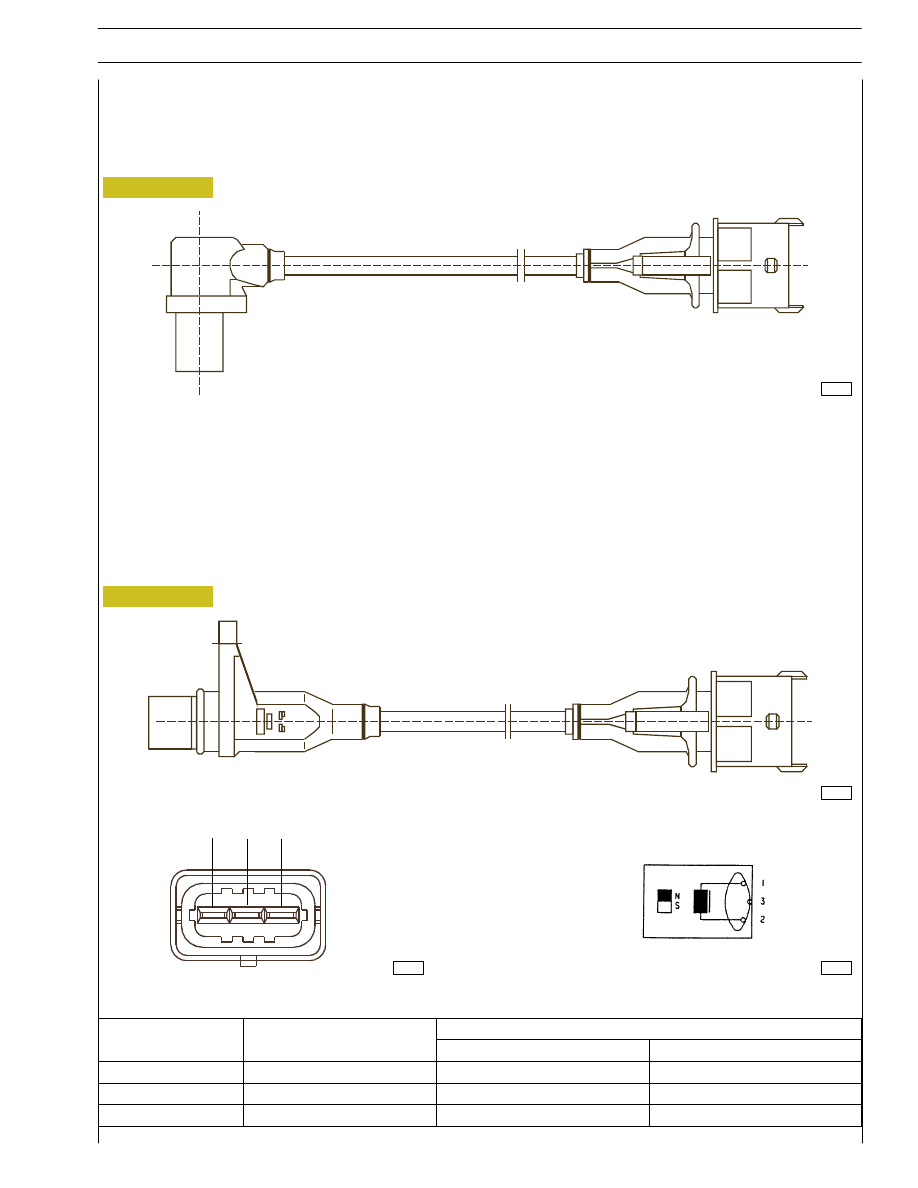
Figure 99
Crankshaft sensor
Crankshaft sensor
This is an inductive sensor located at the front left hand side of the engine. The crankshaft sensor produces signals obtained from
a magnetic flux field closing through the openings in a phonic wheel fitted on the crankshaft.
The crankshaft sensor is connected to the control unit on pins 19C - 23C. The sensor impedance is
∼900 Ω.
50319
Timing sensor
This is an inductive sensor located at the rear left hand side of the engine. The timing sensor generates signals obtained from a
magnetic flux field closing through the holes in the timing gear on the camshaft. The signal generated by this sensor is utilized by
the electronic control unit as an injection phase signal.
Although it is similar to the flywheel sensor, these two devices are NOT interchangeable because of the different external shape.
The timing sensor is connected to the control unit on pins 9C - 10C. The sensor impedance
is
∼900 Ω.
Figure 100
50288
50342
Connector
Wiring diagram
50320
Timing sensor
3
1
2
SECTION 3 - DUTY-INDUSTRIAL APPLICATION
37
F4HE NEF ENGINES
Print P2D32N003GB
Base - February 2006
Ref
Description
ECU pin
Ref.
Description
Camshaft sensor
Timing sensor
1
Signal
19C
10C
2
Signal
23C
9C
3
Shield
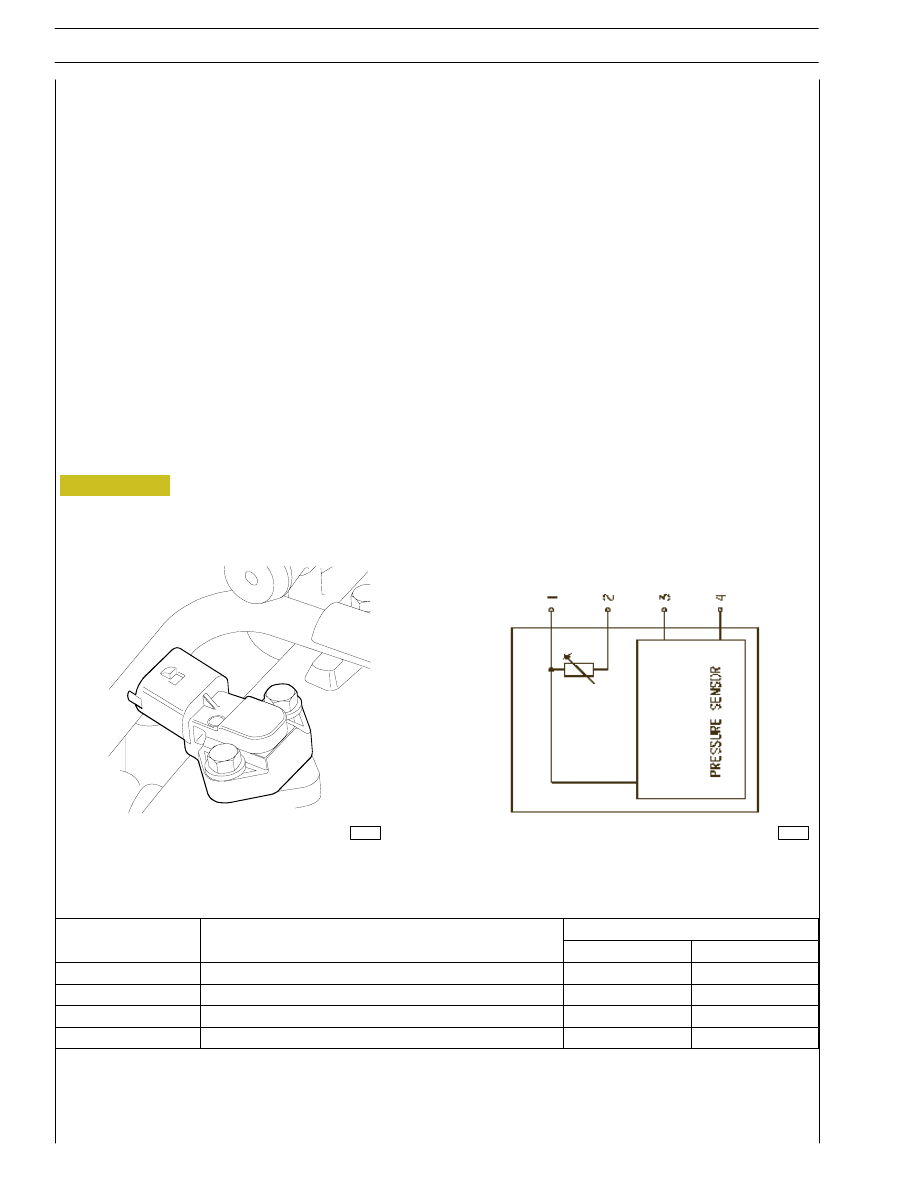
Supercharging air pressure - temperature sensor
This component incorporates a temperature sensor and a pressure sensor.
Mounted on the intake manifold, the sensor measures the maximum flow rate of air supplied, which serves to make an accurate
calculation of the quantity of fuel to be injected in each cycle.
The sensor is connected to the control unit on pins 25C - 36C - 33C - 34C.
The power supply is 5 volt
Voltage at the sensor output is proportional to the detected pressure or temperature.
Pin 25C - 36C
Temperature
Pin 33C - 34C
Pressure
Engine oil temperature-pressure sensor
This component is analogous to the air temperature-pressure sensor.
The engine oil temperature-pressure sensor is installed on the engine oil filter support in a vertical position.
This sensor measures the engine oil temperature and pressure.
The sensor is connected to the control unit on pins 24C - 28C - 32C - 27C.
The sensor is supplied with 5 Volts. The signal detected is transmitted to the EDC control unit which, in turn, controls the relative
device on the instrument panel (gauge + low pressure warning light).
The oil temperature is not displayed on any gauges - this value is used exclusively by the control unit.
Pin 24C - 28C
Temperature
Pin 32C - 27C
Pressure
Figure 101
50344
50324
Wiring diagram
38
SECTION 3 - DUTY-INDUSTRIAL APPLICATION
F4HE NEF ENGINES
Base - February 2006
Print P2D32N00GB
Ref
Description
ECU Pin
Ref.
Description
Oil
Air
1
Ground
24C
25C
2
NTC signal (temperature)
28C
36C
3
+5 V power input
32C
34C
4
Signal (pressure)
27C
34C
Нет комментариевНе стесняйтесь поделиться с нами вашим ценным мнением.
Текст