Engines Iveco N45, N67. Manual — part 27
70184
70185
70187
Figure 31
Figure 32
Figure 33
Figure 34
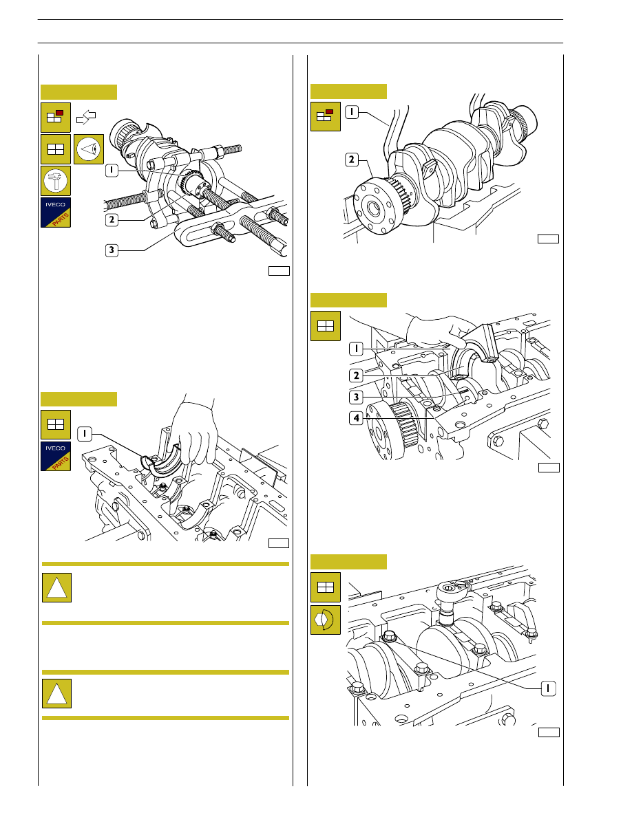
Refit the crankshaft (2).
Check the backlash between crankshaf main journals and the
relevant bearings as follows:
Tighten the pre-lubricated screws (1) in the following three
successive stages:
- 1
st
stage, with torque wrench to 50
± 6 Nm.
- 2
nd
stage, with torque wrench to 80
± 6 Nm.
!
Refit the main bearings that have not been replaced,
in the same position found at removal.
Fitting main bearings
!
Do not try to adapt the bearings.
Main bearings (1) are supplied spare with 0.250 — 0.500 mm
undersize on the internal diameter.
Clean accurately the main half bearings (1) having the
lubricating hole and fit them into their housings.
The second last main half bearing (1) is fitted with shoulder
half rings.
Check that gear toothing (1) is not damaged or worn,
otherwise remove it using the proper puller (3).
When fitting the new gear, heat it to 180
°C for 10 minutes
in an oven and then key it to the crankshaft.
Figure 35
- clean accurately the parts and remove any trace of oil;
- position a piece of calibrated wire (3) on the crankshaft
pins (4) so that it is parallel to the longitudinal axis;
- fit caps (1), including the half bearings (2) on the relevant
supports.
70186
70161
Replacing oil pump control gear
Finding journal clearance
22
SECTION 4 - OVERHAUL AND TECHNICAL SPECIFICATIONS
F4HE NEF ENGINES
Base - February 2006
Print P2D32N00GB
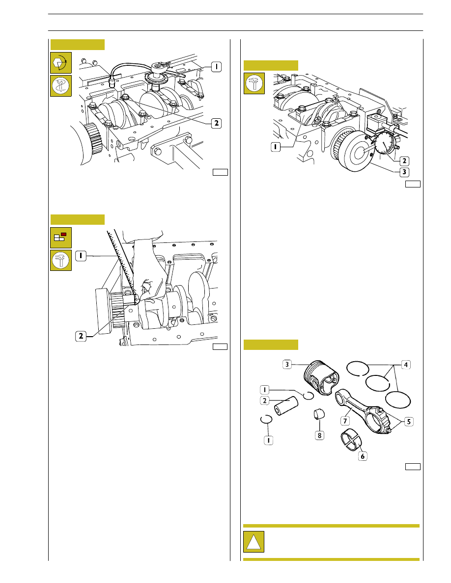
This check is performed by setting a magnetic-base dial gauge
(2) on the crankshaft (3) as shown in the figure, standard
value is 0.068 to 0.41.
If higher value is found, replace main thrust half bearings of
the second last rear support (1) and repeat the clearance
check between crankshaft pins and main half bearings.
70188
70189
70190
70191
Figure 36
Figure 37
Figure 38
Figure 39
- 3
rd
stage, with tool 99395216 (1) set as shown in the
figure, tighten the screws (2) with 90
± 5° angle.
- Remove caps from supports.
The backlash between the main bearings and the pins is
found by comparing the width of the calibrated wire (2) at
the narrowest point with the scale on the envelope (1)
containing the calibrated wire.
The numbers on the scale indicate the backlash in mm.
Replace the half bearings and repeat the check if a different
backlash value is found. Once the specified backlash is
obtained, lubricate the main bearings and fit the supports by
tightening the fastening screws as previously described.
CONNECTING ROD — PISTON ASSEMBLY
COMPONENTS
1. Stop rings - 2. Pin - 3. Piston - 4. Split rings - 5. Screws -
6. Half bearings - 7. Connecting rod - 8. Bush.
α
Checking crankshaft shoulder clearance
!
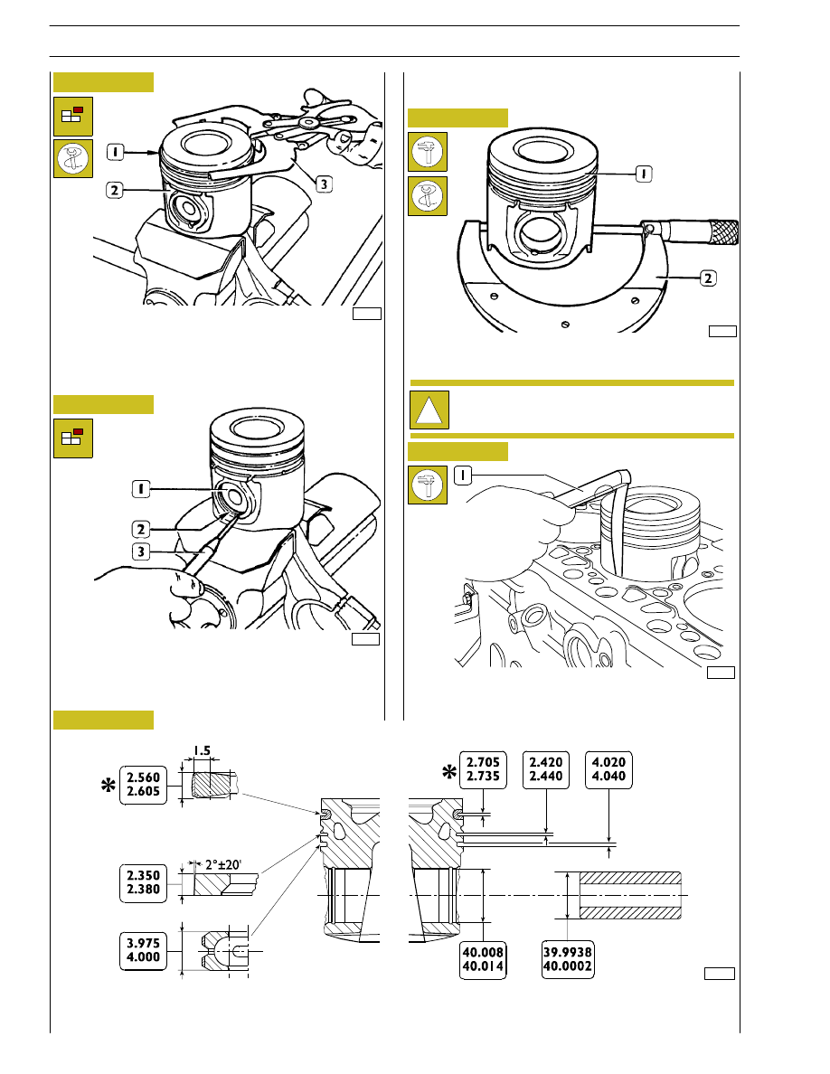
Pistons are supplied from parts with 0.5 mm oversize.
CONNECTING ROD — PISTON ASSEMBLY
SECTION 4 - OVERHAUL AND TECHNICAL SPECIFICATIONS
23
F4HE NEF ENGINES
Print P2D32N003GB
Base - February 2006
32615
32614
32613
70192
Figure 40
Figure 41
Figure 42
Figure 43
Figure 44
Remove split rings (1) from piston (2) using pliers 99360183
(3).
Piston pin (1) split rings (2) are removed using a scriber (3).
Using a micrometer (2), measure the diameter of the piston
(1) to determine the assembly clearance.
The clearance between the piston and the cylinder barrel can
be checked also with a feeler gauge (1) as shown in the figure.
!
The diameter shall be measured at 12 mm from the
piston skirt.
MAIN DATA CONCERNING KS. PISTON, PINS AND SPLIT RINGS
* Value measured on 99 mm diameter
Pistons
Measuring piston diameter
107270
24
SECTION 4 - OVERHAUL AND TECHNICAL SPECIFICATIONS
F4HE NEF ENGINES
Base - February 2006
Print P2D32N00GB
32620
16552
32619
18857
Figure 45
Figure 46
Figure 47
Figure 48
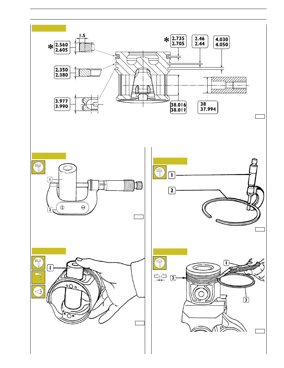
To measure the piston pin (1) diameter use the micrometer
(2).
Lubricate the pin (1) and its seat on piston hubs with engine
oil; the pin shall be fitted into the piston with a slight finger
pressure and shall not be withdrawn by gravity.
Use a micrometer (1) to check split ring (2) thickness.
Check the clearance between the sealing rings (3) of the 2
nd
and 3
rd
slot and the relevant housings on the piston (2), using
a feeler gauge (1).
Piston pins
Figure 49
86497
MAIN DATA CONCERNING MONDIAL MAHLE PISTON, PINS AND SPLIT RINGS
* Value measured on 101 mm diameter
Conditions for proper pin-piston coupling
SECTION 4 - OVERHAUL AND TECHNICAL SPECIFICATIONS
25
F4HE NEF ENGINES
Print P2D32N003GB
Base - February 2006
Нет комментариевНе стесняйтесь поделиться с нами вашим ценным мнением.
Текст