Engines Iveco N45, N67. Manual — part 28
41104
Figure 50
Figure 51
Figure 52
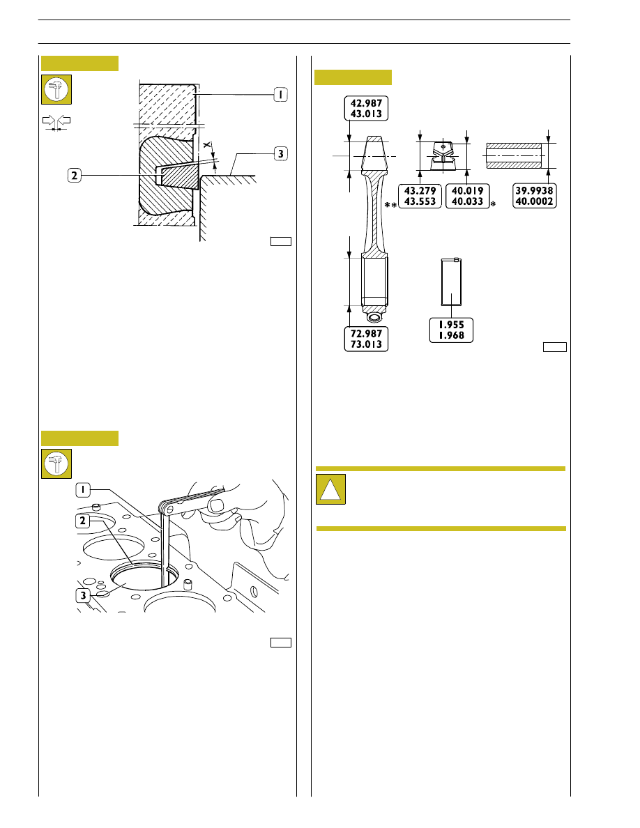
Use a micrometer (1) to check split ring (2) thickness.
DIAGRAM FOR MEASURING THE CLEARANCE X
BETWEEN THE FIRST PISTON SLOT AND THE
TRAPEZOIDAL RING
Since the first sealing ring section is trapezoidal, the clearance
between the slot and the ring shall be measured as follows:
make the piston (1) protrude from the engine block so that
the ring (2) protrudes half-way from the cylinder barrel (3).
In this position, use a feeler gauge to check the clearance (X)
between ring and slot: found value shall be the specified one.
70194
Use feeler gauge (1) to measure the clearance between the
ends of the split rings (2) fitted into the cylinder barrel (3).
MAIN DATA FOR CONNECTING ROD, BUSH, PISTON
PIN AND HALF BEARINGS
Connecting rods
* Value for inside diameter to be obtained after driving in
connecting rod small end and grinding.
** Value not measurable in released condition
!
The surface of connecting rod and rod cap are
knurled to ensure better coupling.
Therefore, it is recommended not to smooth the
knurls.
107271
26
SECTION 4 - OVERHAUL AND TECHNICAL SPECIFICATIONS
F4HE NEF ENGINES
Base - February 2006
Print P2D32N00GB
70196
Figure 53
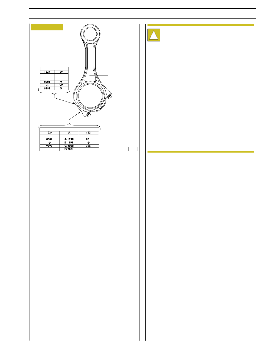
Bushes
Check that the bush in the connecting rod small end is free
from scoring or seizing and that it is not loosen. Otherwise
replace.
Removal and refitting shall be performed using the proper
beater.
When refitting take care to make coincide the oil holes set
on the bush with those set on the connecting rod small end.
Grind the bush to obtain the specified diameter.
!
Every connecting rod is marked as follows:
- On body and cap with a number showing their
coupling and the corresponding cylinder.
In case of replacement it is therefore necessary
to mark the new connecting rod with the same
numbers of the replaced one.
- On body with a letter showing the weight of the
connecting rod assembled at production:
S
V, 1820 to 1860 (yellow marking);
S
W, 1861 to 1900 (green marking);
S
X, 1901 to 1940 (blue marking);
Spare connecting rods are of the W class with green
marking *.
Material removal is not allowed.
*
CONNECTING ROD BODY
CONNECT-
ING ROD
BODY
CONNECT-
ING ROD
BODY
CONNECT-
ING ROD
BODY
CONNECT-
ING ROD
BODY
CONNECTING ROD
BODY
CONNECTING ROD BODY
SECTION 4 - OVERHAUL AND TECHNICAL SPECIFICATIONS
27
F4HE NEF ENGINES
Print P2D32N003GB
Base - February 2006
61696
61694
61695
70198
Figure 54
Figure 55
Figure 56
Figure 57
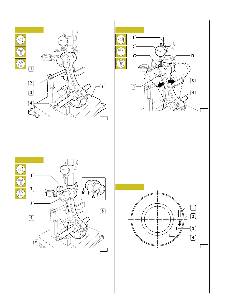
Check that the axis of the connecting rods (1) are parallel
using tool 99395363 (5) as follows:
- fit the connecting rod (1) on tool 99395363 (5) spindle
and lock it with screw (4);
- set the spindle (3) on V-blocks by resting the connecting
rod (1) on the stop bar (2).
Check connecting rod (5) torsion by comparing two points
(A and B) of pin (3) on the horizontal plane of the connecting
rod axis.
Position the dial gauge (2) support (1) to obtain a preload of
approx. 0.5 mm on the pin (3) in point A and then set the
dial gauge (2) to zero. Move the spindle (4) with the
connecting rod (5) and compare any deviation on the
opposite side (B) of the pin (3): the difference between A and
B shall not exceed 0.08 mm.
Check connecting rod (5) bending by comparing two points
C and D of the pin (3) on the vertical plane of the connecting
rod axis.
Position the vertical support (1) of the dial gauge (2) to rest
the latter on pin (3), point C.
Move the connecting rod forwards and backwards to find pin
top position, then in this condition reset the dial gauge (2).
Move the spindle with the connecting rod (5) and repeat the
check of the top point on the opposite side D of the pin (3).
The difference between point C and point D shall not exceed
0.08 mm.
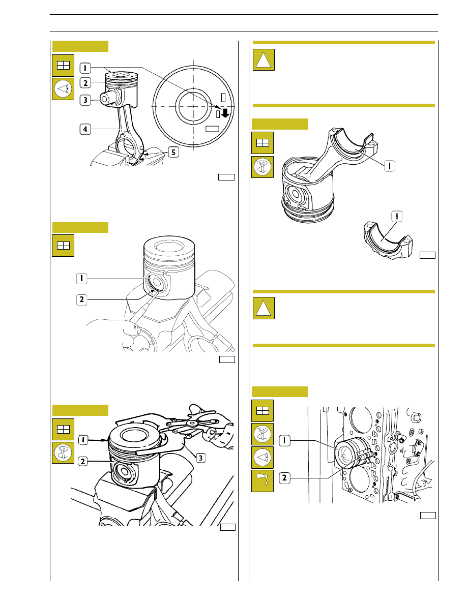
Fitting connecting rod-piston assembly
Connecting rod-piston coupling
The piston crown is marked as follows:
1.
Part number and design modification number;
2.
Arrow showing piston assembling direction into cylinder
barrel, this arrow shall face the front key of the engine
block;
3.
Marking showing 1
st
slot insert testing;
4.
Manufacturing date.
Checking connecting rods
Checking bending
Checking torsion
28
SECTION 4 - OVERHAUL AND TECHNICAL SPECIFICATIONS
F4HE NEF ENGINES
Base - February 2006
Print P2D32N00GB
72705
32613
70200
70201
Figure 58
Figure 59
Figure 60
Figure 61
Figure 62
Connect piston (2) to connecting rod (4) with pin (3) so that
the reference arrow (1) for fitting the piston (2) into the
cylinder barrel and the numbers (5) marked on the
connecting rod (5) are read as shown in the figure.
Position the piston (1) on the connecting rod according to
the diagram shown in the figure, fit the pin (3) and stop it by
the split rings (2).
Fitting split rings
Use pliers 99360183 (3) to fit the split rings (1) on the piston
(2).
Split rings shall be fitted with the marking “TOP” facing
upwards and their openings shall be displaced with each
other by 120
°.
Fit half bearings (1) on connecting rod and cap.
Lubricate accurately the pistons, including the split rings and
the cylinder barrel inside.
Use band 99360605 (2) to fit the connecting rod-piston
assembly (1) into the cylinder barrels and check the following:
- the number of each connecting rod shall correspond to
the cap coupling number.
!
Split rings are supplied spare with the following sizes:
-
standard, yellow marking;
-
0.5 mm oversize, yellow/green marking;
Fitting connecting rod-piston assembly into
cylinder barrels
!
Refit the main bearings that have not been replaced,
in the same position found at removal.
Do not try to adapt the half bearings.
108597
SECTION 4 - OVERHAUL AND TECHNICAL SPECIFICATIONS
29
F4HE NEF ENGINES
Print P2D32N003GB
Base - February 2006
Нет комментариевНе стесняйтесь поделиться с нами вашим ценным мнением.
Текст