Engines Iveco N45, N67. Manual — part 36
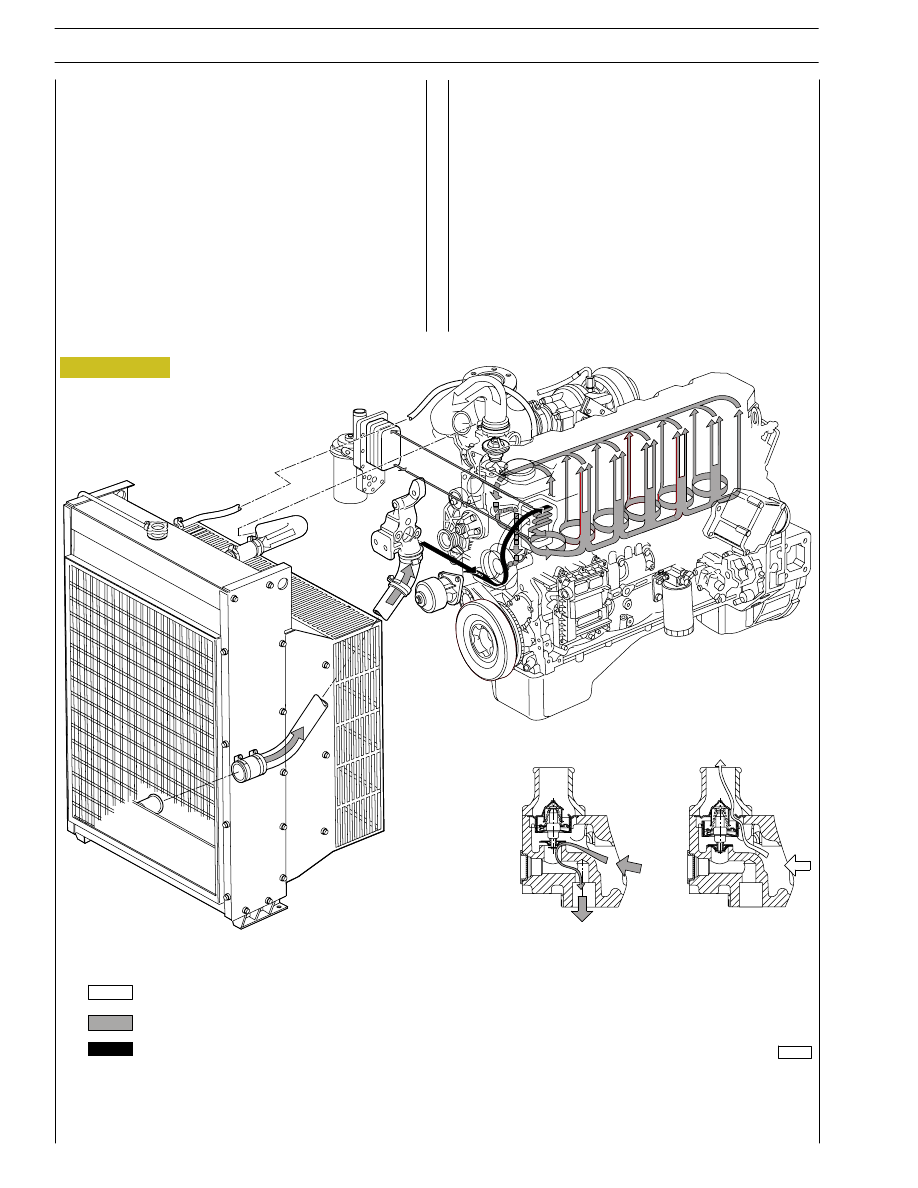
Figure 1
106529
Water leaving the thermostat
Coolant recirculating in the engine
Water entering the pump
DIAGRAM OF THE COOLING SYSTEM
COOLING SYSTEM
The engine cooling system, closed circuit forced circulation
type, generally incorporates the following components:
- Expansion tank; placement, shape and dimensions are
subject to change according to the engine’s equipment.
- Radiator, which has the duty to dissipate the heat
subtracted to the engine by the cooling liquid. Also this
component will have specific peculiarities based on the
equipment developed, both for what concerns the
placement and the dimensions.
- Viscous pusher fan, having the duty to increase the heat
dissipating power of the radiator. This component as well
will be specifically equipped based on the engine’s
development.
- Heat exchanger to cool the lubrication oil: even this
component is part of the engine’s specific equipment.
- Centrifugal water pump, placed in the front part of the
engine block.
- Thermostat regulating the circulation of the cooling liquid.
- The circuit may eventually be extended to the
compressor, if this is included in the equipment.
8
SECTION 1 - GENERAL SPECIFICATIONS
G-DRIVE ENGINES
Base - February 2006
Print P2D32N00GB

Figure 2
AIR INDUCTION - BOOST DIAGRAM
Description
The turbocharger is composed by the following main parts:
one turbine, one transforming valve to regulate the boost
feeding pressure , one main body and one compressor.
During engine working process, the exhaust emissions flow
through the body of the turbine, causing the turbine disk
wheel’s rotation.
The compressor rotor, being connected by shaft to the
turbine disk wheel, rotates as long as this last one rotates,
compressing the drawn air through the air filter.
The above mentioned air is then cooled by the radiator and
flown through the piston induction collector.
The turbocharger is equipped with a transforming valve to
regulate the pressure , that is located on the exhaust collector
before the turbine and connected by piping to the induction
collector.
It’s funchon is to restrict the exhaust of the emissions , releasing
part of them directly to the exhaust tube when the boost
feeding pressure, over the compressor, reaches the
prescribed bar value.
The cooling process and the lubrication of the turbocharger
and of the bearings is made by the oil of the engine.
106548
Compressed air to the heat exchanger
Refrigerated compressed air to the pistons
Exhaust gas
Intake air
TURBOCHARGING DIAGRAM
SECTION 1 - GENERAL SPECIFICATIONS
9
G-DRIVE ENGINES
Print P2D32N003GB
Base - February 2006
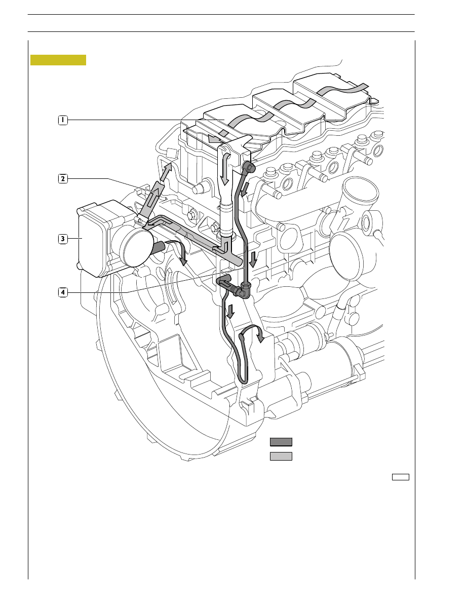
Figure 3
1. Pre-separator - 2. Exhaust to the outside (temporary) - 3. Filter - 4. Return to engine.
The tappet cover houses the pre-separator (1), whose shape and position determines an increase in oil vapour outlet speed and
condenses a part of vapours at the same time.
Condensate oil returns to the oil sump whereas the residual vapours are ducted, collected and filtered in the blow-by (3).
In the blow-by (3), part of the vapours condense and return to the oil sump whereas the remaining part is put into cycle again
through pipe (2).
Oil condensate
Oil vapours
OIL VAPOUR RECYCLING
108729
10
SECTION 1 - GENERAL SPECIFICATIONS
G-DRIVE ENGINES
Base - February 2006
Print P2D32N00GB

SECTION 2 - G-DRIVE APPLICATION
11
G-DRIVE ENGINES
Print P2D32N003GB
Base - February 2006
GENERAL SPECIFICATIONS
Type
FAHE9685A
Cycle
Four-stroke diesel engine
Power
Supercharged with intercooler
Injection
Direct
Number of cylinders
6
∅
Bore
mm
104
Stroke
mm
132
+
+
+.. =
Total displacement
cm
3
6728
TIMING
start before T.D.C.
A
end after B.D.C.
B
18.5º
29.5º
start before B.D.C.
D
end after T.D.C.
C
67º
35º
X
Checking timing
mm
X
mm
Checking operation
mm
X
mm
-
-
0.20 to 0.30
0.45 to 0.55
FUEL FEED
Injection
Type:
Bosch
high pressure common rail
EDC7 ECU
Nozzle type
Injectors
Injection sequence
1 - 5 - 3 - 6 - 2 - 4
bar
Injection pressure
bar
250
÷ 1450
Нет комментариевНе стесняйтесь поделиться с нами вашим ценным мнением.
Текст