Engines Iveco N45, N67. Manual — part 37

!
Data, features and performances are valid only if the technician fully complies with all the installation requirements provided
by Iveco Motors.
Furthermore, the use of the unit after overhaul showd conform to the original specified power and engine rev/min for
which the engine has been designed.
12
SECTION 2 - G-DRIVE APPLICATION
G-DRIVE ENGINES
Base - February 2006
Print P2D32N00GB
Clearance data - 6 cyl.
FAHE9685A
Type
FAHE9685A
ρ
Compression ratio
17 : 1
Max. output
kW
(HP)
rpm
215
292
1800
Max. torque
Nm
(kgm)
rpm
-
-
-
Loadless engine
idling
rpm
-
Loadless engine
peak rpm
rpm
-
Bore x stroke
Displacement
104 x 132
6728
TURBOCHARGING
Turbocharger type
with intercooler
HOLSET HX35W
bar
LUBRICATION
Oil pressure (warm engine)
- idling
bar
Forced by gear pump, relief valve single action
oil filter
- peak rpm
bar
2
4
COOLING
Water pump control
Thermostat
- start of opening
ºC
By liquid
Through belt
81
± 2
15W40 ACEA E3
FILLING
engine sump
liters
engine sump + filter
liters
15
15 + 1
SECTION 2 - G-DRIVE APPLICATION
13
G-DRIVE ENGINES
Print P2D32N003GB
Base - February 2006
CLEARANCE DATA
Type
6 CYLINDERS
CYLINDER UNIT AND CRANKSHAFT COMPONENTS
mm
∅1
X
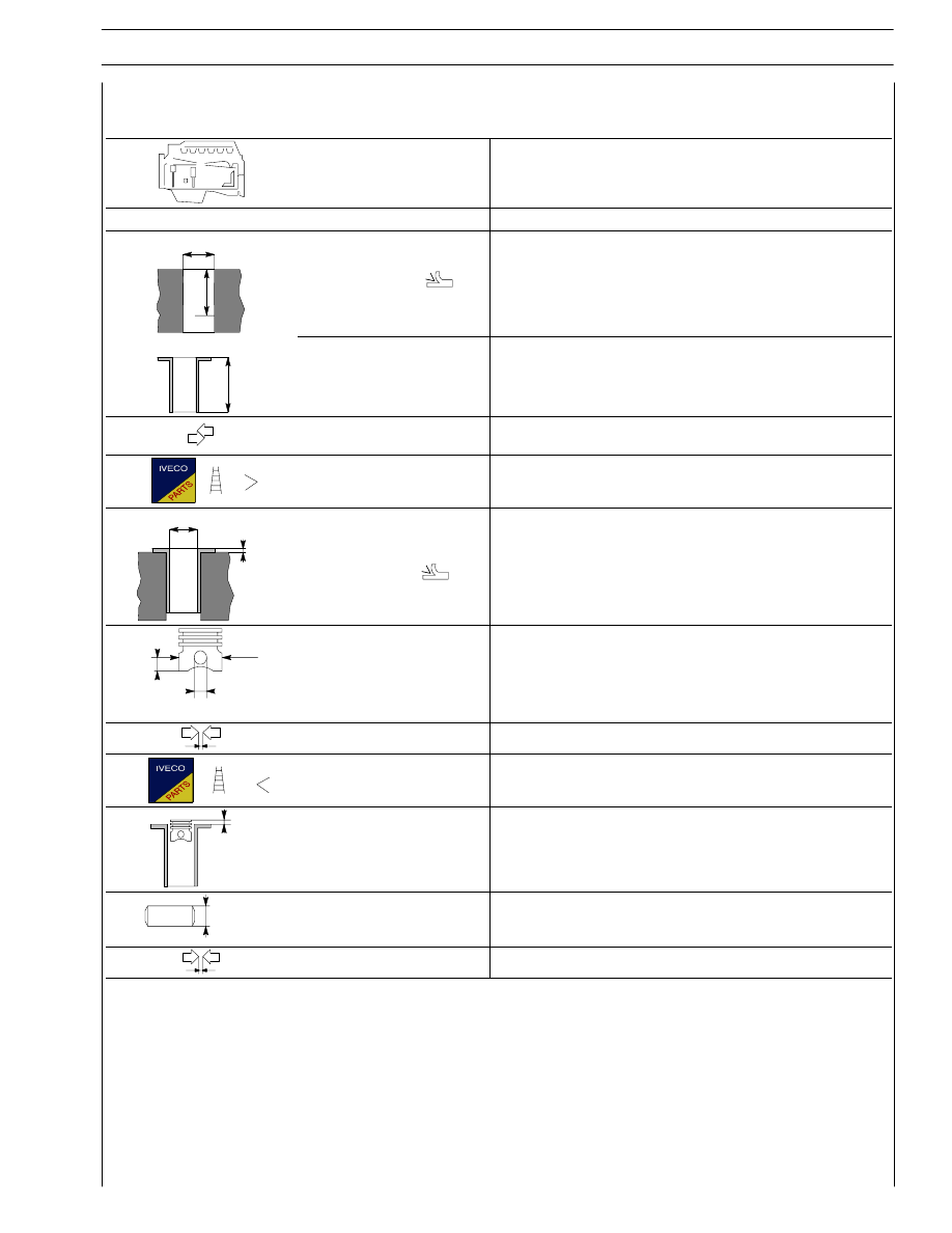
Cylinder barrels
∅1
103.99 to 104.010
L
∅
Cylinder barrels:
outside diameter
∅ 2
length
L
-
-
Cylinder barrels — housings on
engine block (interference)
-
Outside diameter
∅ 2
0.5
∅ 3
X
Cylinder barrels:
inside diameter
∅ 2
-
∅1
X
∅ 2
Spare pistons
type:
Size
X
Outside diameter
∅ 1
Pin housing
∅ 2
12
103.851 to 103.865
40.00 to 40.25
Piston — cylinder barrels
0.113 to 0.147
Piston diameter
∅ 1
0.5
X
Piston protrusion
X
0.28 to 0.52
3
∅
Piston pin
∅ 3
37.994 to 38
Piston pin — pin housing
0.0006 to 0.0202
14
SECTION 2 - G-DRIVE APPLICATION
G-DRIVE ENGINES
Base - February 2006
Print P2D32N00GB
Type
6 CYLINDERS
CYLINDER UNIT AND CRANKSHAFT COMPONENTS
mm
X
1
3
2
X
X
X1*
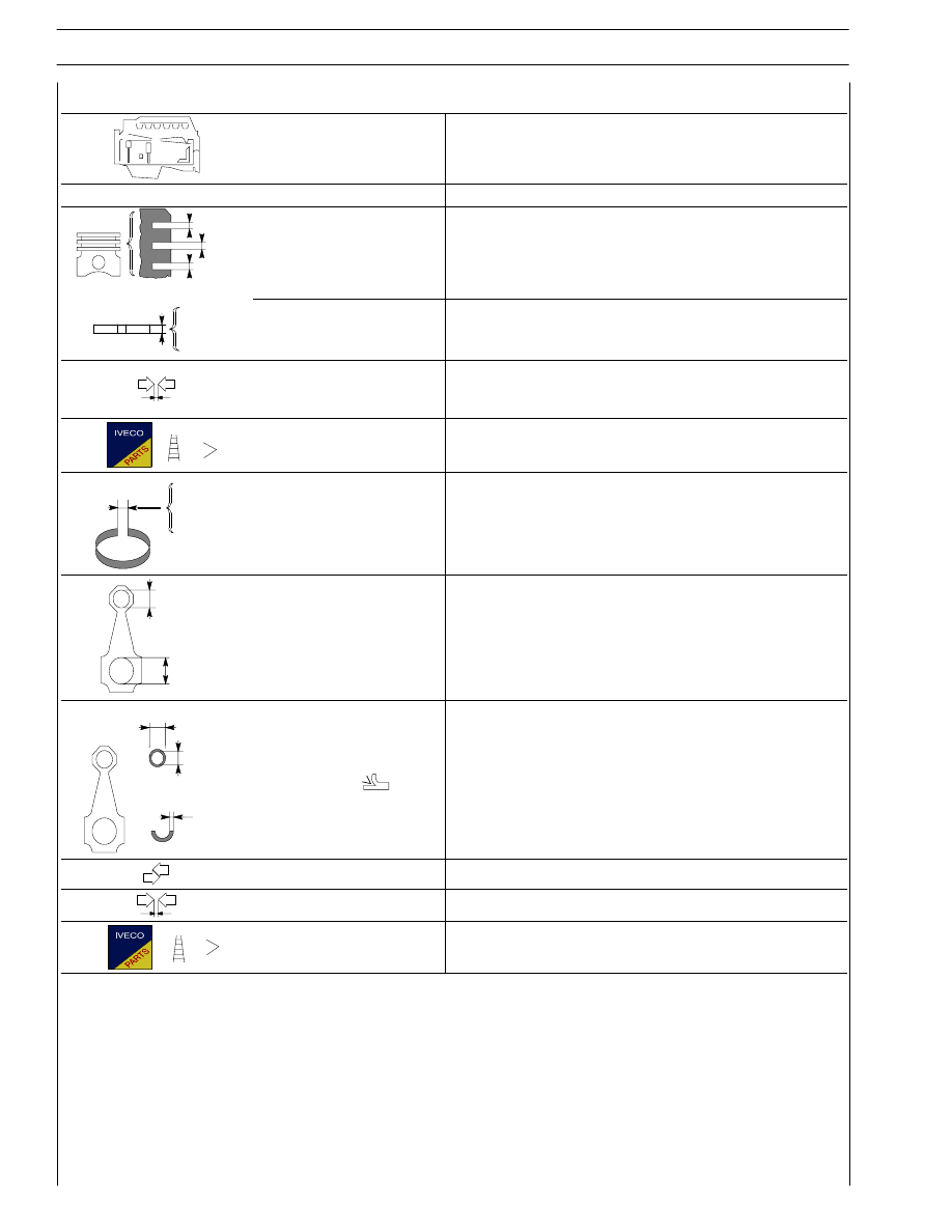
Split ring slots
X 2
X 3
* measured on 99 mm
∅
3
2.42 to 2.44
4.03 to 4.05
1
3
2
S
S
S
S 1*
Split rings
S 2
S 3
3
2.350 to 2.380
4.030 to 4.050
1
Split rings - slots
2
3
0.100 to 0.175
0.040 to 0.90
0.020 to 0.065
Split rings
0.5
X 1
3
2
X
X
Split ring end opening
in cylinder barrel:
X 1
X 2
X 3
0.30 to 0.40
0.60 to 0.80
0.3 to 0.55
1
∅
∅ 2
Small end bush
housing
∅ 1
Big end bearing
housing
∅ 2
42.987 to 43.013
72.987 to 73.013
∅
S
∅ 4
3
Small end bush diameter
Outside
∅ 4
Inside
∅ 3
Spare big end half
bearings
S
40.987 to 41.013
38.019 to 38.033
1.955 to 1.968
Small end bush — housing
0.266 to 0.566
Piston pin — bush
0.0188 to 0.0372
Big end half bearings
0.250; 0.500; 0.750; 1.000
SECTION 2 - G-DRIVE APPLICATION
15
G-DRIVE ENGINES
Print P2D32N003GB
Base - February 2006
Type
6 CYLINDERS
CYLINDER UNIT AND CRANKSHAFT COMPONENTS
mm
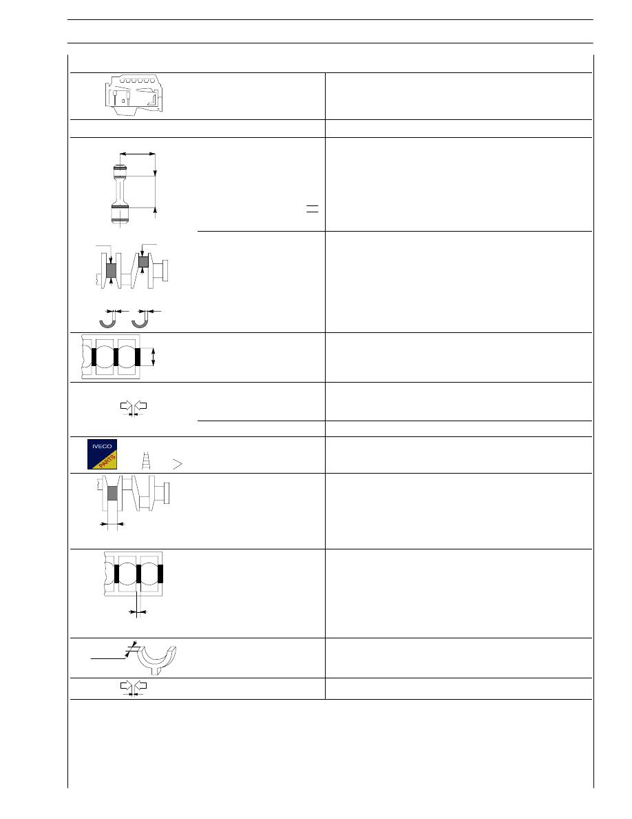
X
Size
X
Max. tolerance
on connecting rod
axis alignment
-
-
1
2
∅
∅
S 1
S 2
Journals
∅ 1
Crankpins
∅ 2
Main half bearings
S 1
Big end half bearings
S 2
*provided as spare part
82.99 to 83.01
73.533 to 74.513
2.456 to 2.464
1.955 to 1.968
3
∅
Main bearings
No. 1—7
∅ 3
No. 2—3—4—5—6
∅ 3
87.982 to 88.008
87.977 to 88.013
Half bearings — Journals
No. 1—7
No. 2—3—4—5—6
0.044 to 0.106
0.039 to 0.111
Half bearings - Crankpins
0.038 to 0.116
Main half bearings
Big end half bearings
+0.250; +0.500; +0.750; +1.000
1
X
Shoulder journal
X 1
37.28 to 37.38
X 2
Shoulder main bearing
X 2
28.77 to 29.03
X 3
Shoulder half-rings
X 3
37.28 to 37.38
Output shaft shoulder
0.095 to 0.265
Нет комментариевНе стесняйтесь поделиться с нами вашим ценным мнением.
Текст