Engines Iveco N45, N67. Manual — part 10
Disconnect the high pressure fuel pipeline (10, Figure 2) from
the rail diffuser and from the high pressure pump (8) and
disassemble it from the engine block removing the fixing
clamps.
Disconnect the pipeline (7) feeding the mechanic pump that
is combined to the high pressure pump through the
exchanger of the engine control module.
The following information relates to the engine overhaul
operations only for what concerns the different components
customising the engine, according to its specific duties.
In section ”General overhaul”, all the operations of engine
block overhaul have been contemplated. Therefore the
above mentioned section is to be considered as following the
part hereby described.
!
With regard to the engine disassembly operations
from the machine, please apply for Information
consulting the specific manual.
All operations of Engine disassembly operations as
well as overhaul operations must be executed by
qualified technicians provided with the specific
tooling and equipment required.
Figure 2
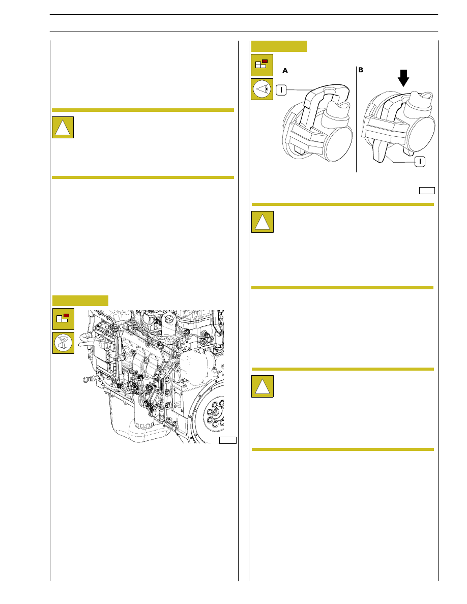
In order to apply the brackets 99341009 to the engine block
to fix it on to the stand for the overhaul, it is necessary to
perform the following operations on the left hand side of the
engine:
- Using the tool 99360073 disassembly the fuel filter (6)
and remove it from the support (1);
- Disconnect the electrical connection (2) from the
support (1) and the heater’s one (placed on the filter
support as well);
- Disconnect the fuel low pressure pipelines (3-4-5) from
the support (1);
- Disconnect pipeline (9) from the support (1);
- Remove the sustaining support bracket (1) from the
block.
70126
Figure 3
!
Press clamp (1), as shown in Figure B, to disconnect
the low pressure fuel pipes (3 — 4 — 5, Figure 2) from
the corresponding connections.
After disconnecting the pipe, reset the clamp (1) in
locking position (Figure A) to prevent distortions.
!
Because of the high pressure in the pipelines running
from the high pressure pump to the rail and from this
last one to the electro-injectors, it is absolutely
required NOT to:
- disconnect the pipelines when the engine is
working;
- re-use the disassembled pipelines.
Engine setting operations for the assembly on
turning stand
ENGINE OVERHAUL
Preface
108541
SECTION 3 - DUTY-INDUSTRIAL APPLICATION
9
F4HE NEF ENGINES
Print P2D32N003GB
Base - February 2006
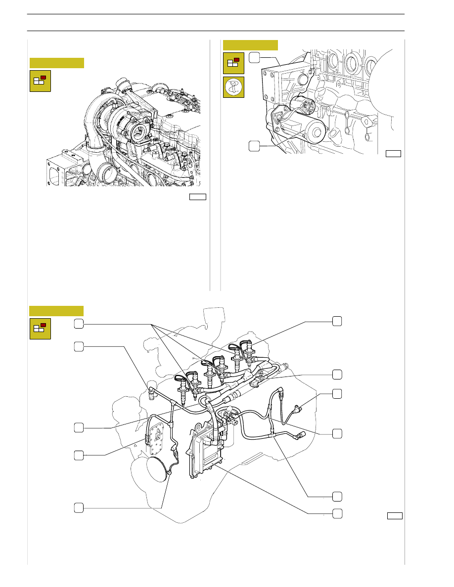
Figure 4
On the right hand side of the engine:
Remove the screws and remove the oil pipe (1) from the
turbocharger pipe (2) and from the engine block.
Disconnect the oil feed pipeline unlocking the three screws
M12x25. Remove the O-ring from the pipe.
Remove the starter (2) from the flywheel housing (1).
Apply brackets 99361037 to engine block and use them to
secure the engine to the revolving stand 99322205. Remove
sump cap and drain out oil.
Remove the fan from the output shaft pulley.
74166
Figure 5
74168
Figure 6
Disassembly of application components
1. Connections for Electro-injectors - 2. Engine cooling liquid temperature’s sensor - 2. Cable of the fuel pressure sensor -
4. Sensor of engine’s oil temperature and pressure - 5. Driving shaft sensor - 6. Electro-injector - 7. Temperature - air
pressure sensor - 8. Timing system sensor - 9. Cable of fuel heater and fuel temperature’s sensor - 10. Cable of pressure
regulating gauge - 11. EDC 7 gearbox.
1
2
1
2
3
4
5
6
7
8
9
10
11
108542
10
SECTION 3 - DUTY-INDUSTRIAL APPLICATION
F4HE NEF ENGINES
Base - February 2006
Print P2D32N00GB
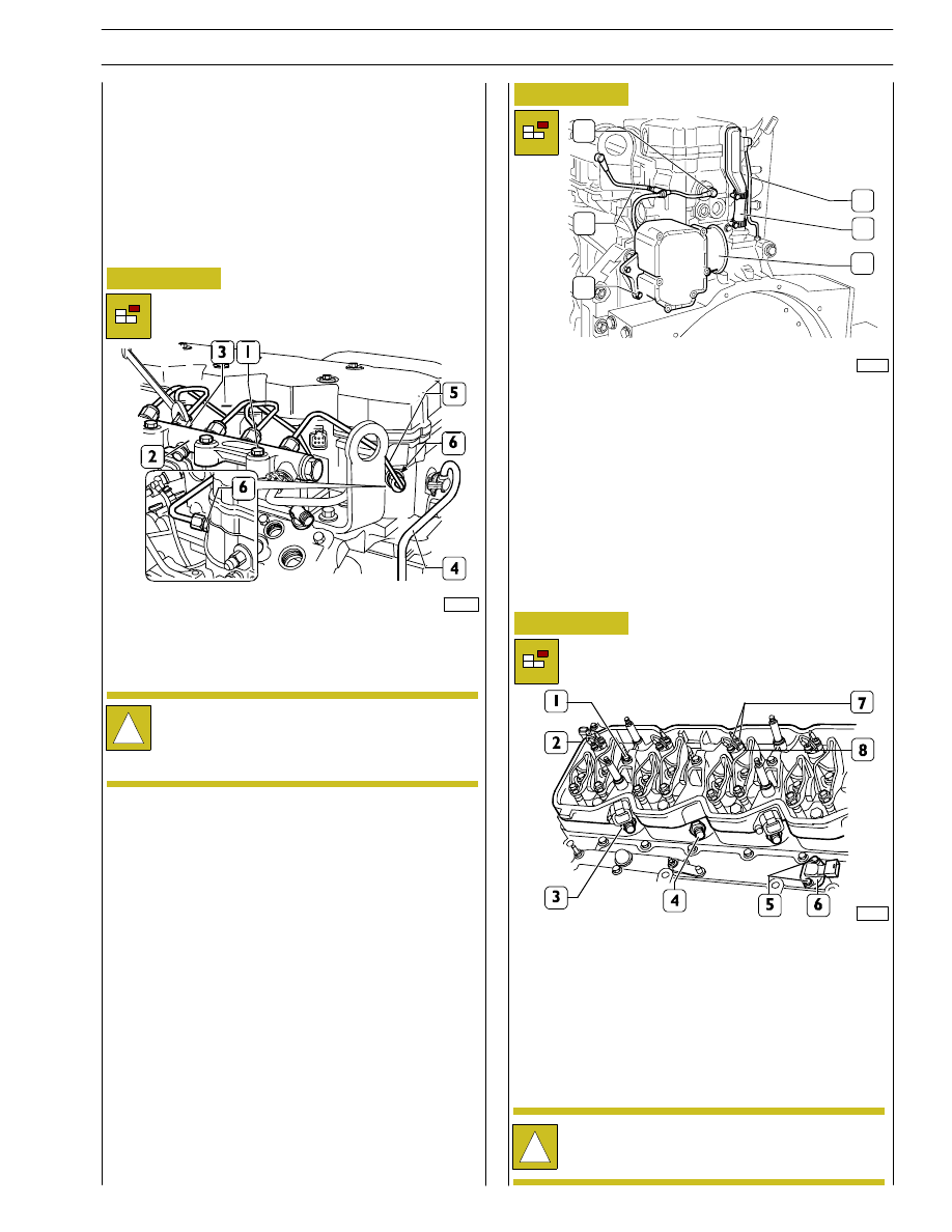
Disconnect the engine’s cable from the connectors (1.
Figure 6) wiring harness to
Electro-injectors (6); (7) air pressure/temperature sensor; (3)
fuel pressure sensor;
(11) engine control module; (10) high pressure pump sensor;
(8) timing system sensor; (2) Thermostat sensor of engine
cooling liquid’s temperature; (5) sensor of engine’s
revolutions.
Figure 7
Remove the screws (1) and disconnect the rail (2).
Disconnect from the rail (2): the fuel pipe (7) according to
procedures described in Figure 3. Disconnect fuel pipes (5)
from rail (2) and injector manifolds (6).
!
When releasing pipe (6) connections (4) to rail (2),
use the proper wrench to avoid rotation of flow
limiters (3).
74170
Disconnect the pipeline (2) from the fuel recover
pressure-limiter, working on the connections as described in
Figure 3.
Unscrew the nut and loosen the clamp tightening the oil
vapour pipe.
Remove the pipe (6).
Loosen the screws (3) and disassemble the blow-by filter (4).
Remove on the nuts and tappet cover.
Figure 8
Figure 9
74744
Remove nuts (7) and disconnect the electrical cables from
injectors (8).
Remove screws (1) and disconnect injector wiring support
(2) including the gasket.
Remove screws (5), disconnect air pressure/temperature
sensor (6).
Remove nuts (3) and remove fuel manifolds (4).
!
Disassembled fuel manifolds (4) must not be used
again, replace with new ones during reassembly.
1
2
3
4
5
6
108543
SECTION 3 - DUTY-INDUSTRIAL APPLICATION
11
F4HE NEF ENGINES
Print P2D32N003GB
Base - February 2006
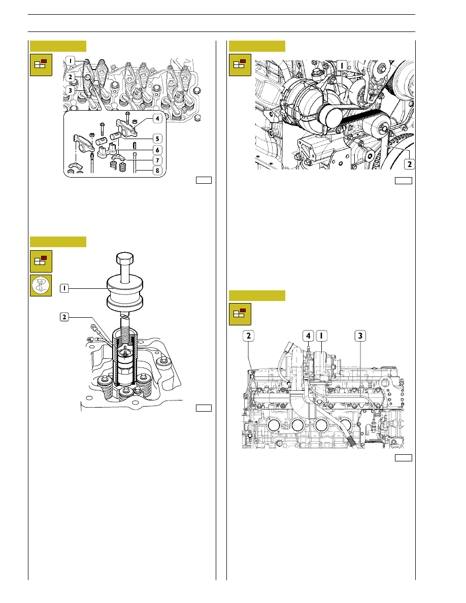
Figure 10
Figure 11
70132
Loosen tappet adjustment fastening nuts (1) and unscrew the
adjusters.
Remove the screws (2), remove the rocker assembly (3),
consisting of: bracket (6), rockers (4), shafts (5) and remove
jumpers (7) from valves.
Remove rods (8).
70133
Remove injector fastening screws. Use tool 99342101 (1) to
remove injectors (2) from the cylinder head.
Release on the drive belt tensioner (1) and extract the belt
(2) from the belt pulleys from the water pump ones and from
the belt rebound pulleys;
Disassemble the belt tensioner;
Loosen the screws fixing the alternator to the support and
disassemble it.
Remove the screw (4) holding the fixing clamp of the
turbocharger’s lubricating oil pipeline.
Disconnect the oil pipeline (3) from the supports of the heat
exchanger / oil filter and from the pipe fitting (5) to the
turbine.
Remove the fixing nuts and disassemble the turbocharger (1)
from the exhaust collector (2).
Loosen the screws and disassemble the exhaust collector (2)
from the cylinder head.
Figure 12
Figure 13
108545
108546
12
SECTION 3 - DUTY-INDUSTRIAL APPLICATION
F4HE NEF ENGINES
Base - February 2006
Print P2D32N00GB
Нет комментариевНе стесняйтесь поделиться с нами вашим ценным мнением.
Текст