Engines Iveco N45, N67. Manual — part 11
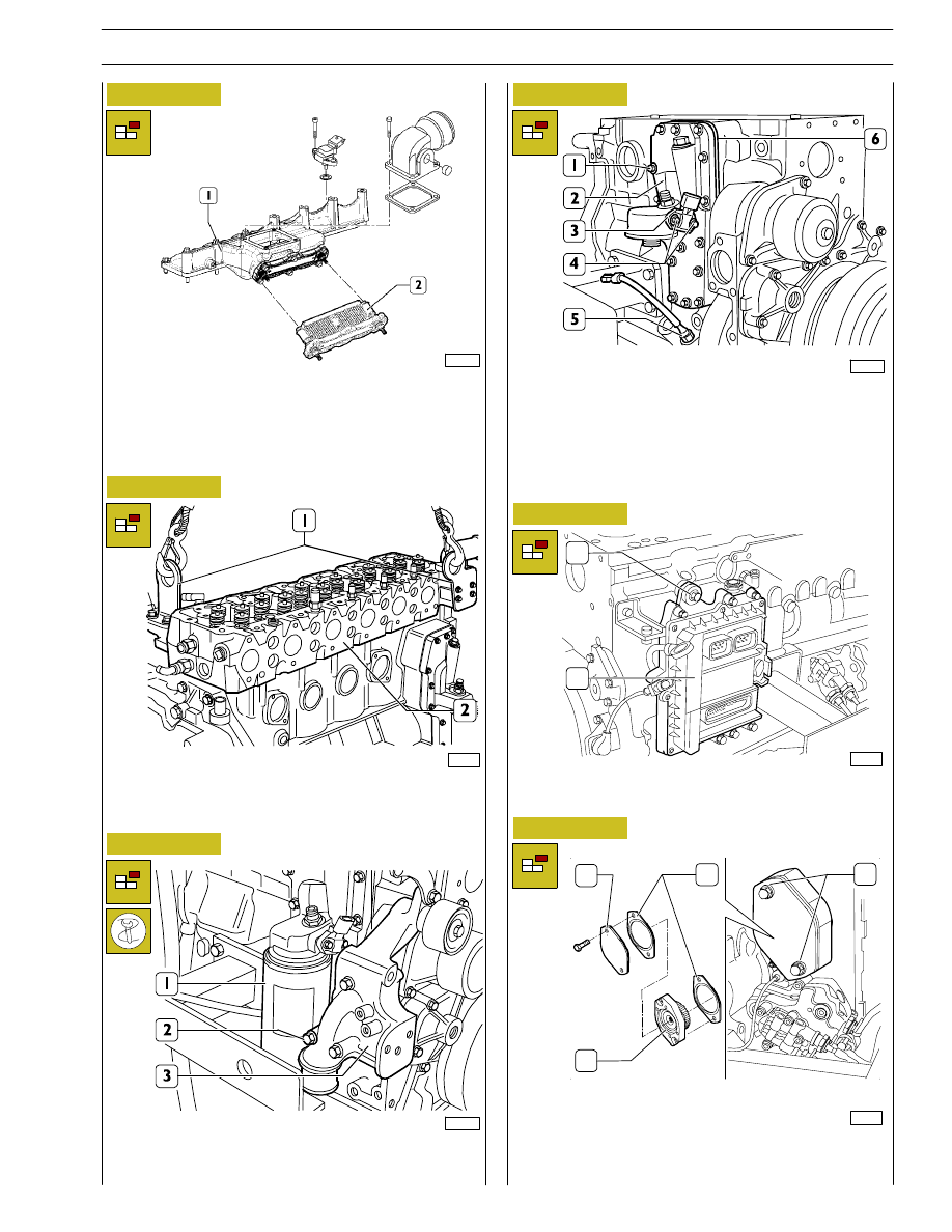
On the opposite side, loosen the fixing screws of the inlet
manifold (1) and disassemble the joint to the air heater (2)
for the cold start.
Figure 14
Figure 15
Remove the screws (2) and disconnect the alternator
support (3).
Use tool 99360076 to remove the oil filter (1).
Figure 16
Hook brackets (1) with suitable lifting chains and remove
cylinder head (2) from block using hoist.
Figure 17
Remove
the
screws
(4)
and
disconnect
the
oil
temperature/pressure sensor (3).
Remove the screws (1) and then remove: heat exchanger/oil
filter support (2), intermediate plate (6) and relevant gaskets.
Remove the oil level sensor (5).
Figure 18
Remove the screws (1) and disconnect the ECU (2) including
the heat exchanger.
74174
Figure 19
Unloose the screws (3) and remove the cap (1). Keep the
gasket (4), the power take-off (2) and the second gasket (4).
74176
1
2
1
2
3
4
108547
74779
108549
108580
SECTION 3 - DUTY-INDUSTRIAL APPLICATION
13
F4HE NEF ENGINES
Print P2D32N003GB
Base - February 2006
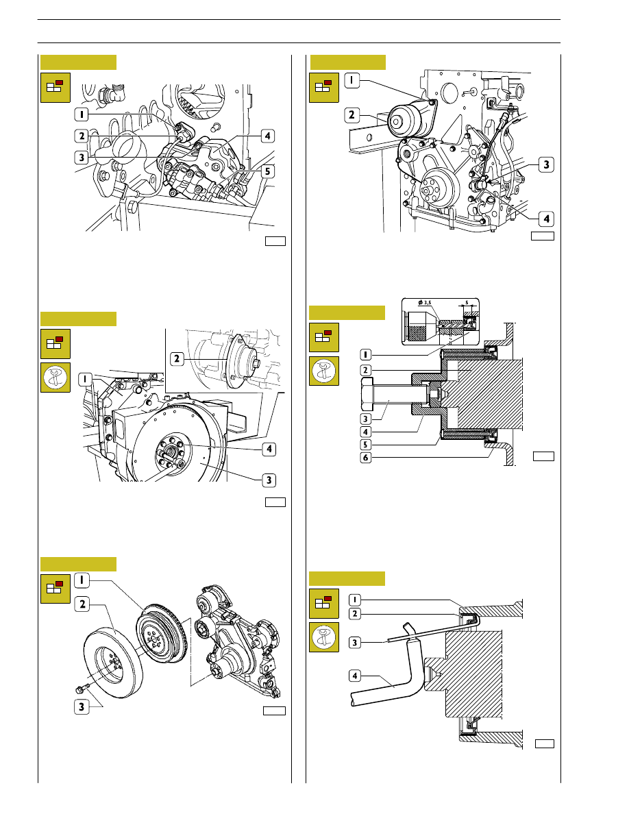
Figure 20
70145
Remove the nut (1) and disconnect the timing sensor (2).
Remove the nuts (3) and disconnect the high pressure pump
(4) including the feed pump (5).
Figure 21
Remove the screws (3) and disassemble the damping
flywheel (2) and the pulley (1).
Figure 22
Figure 23
Remove the screws (1) and disconnect the water pump (2).
Remove the screw (3) and the roller (4).
Remove the screw (3) and disconnect the engine speed
sensor (4).
Remove the ring sealing the engine’s driving shaft from the
front cover. Use the tool 99340055 (4) to operate on the
front bar hold of the driving shaft. Through the steering holes
of the tool, perforate the inside holding ring (1) with a straight
way drill (diam. 3,5mm) for the depth of 5mm. Fix the tool
to the ring tightening the 6 screws provided with the
equipment. Then proceed removing the ring (2) by tightening
the screw (3).
00900t
Figure 24
00904t
Using the specific tie rod (3) of the tool 99363204 and the
ancillary lever (4), remove the external holding ring (2) from
the front cover (1).
70146
Fit tool 99360339 (2) to the flywheel housing (1) to stop
flywheel (3) rotation.
Loosen the screws (4).
Figure 25
108548
108549
14
SECTION 3 - DUTY-INDUSTRIAL APPLICATION
F4HE NEF ENGINES
Base - February 2006
Print P2D32N00GB
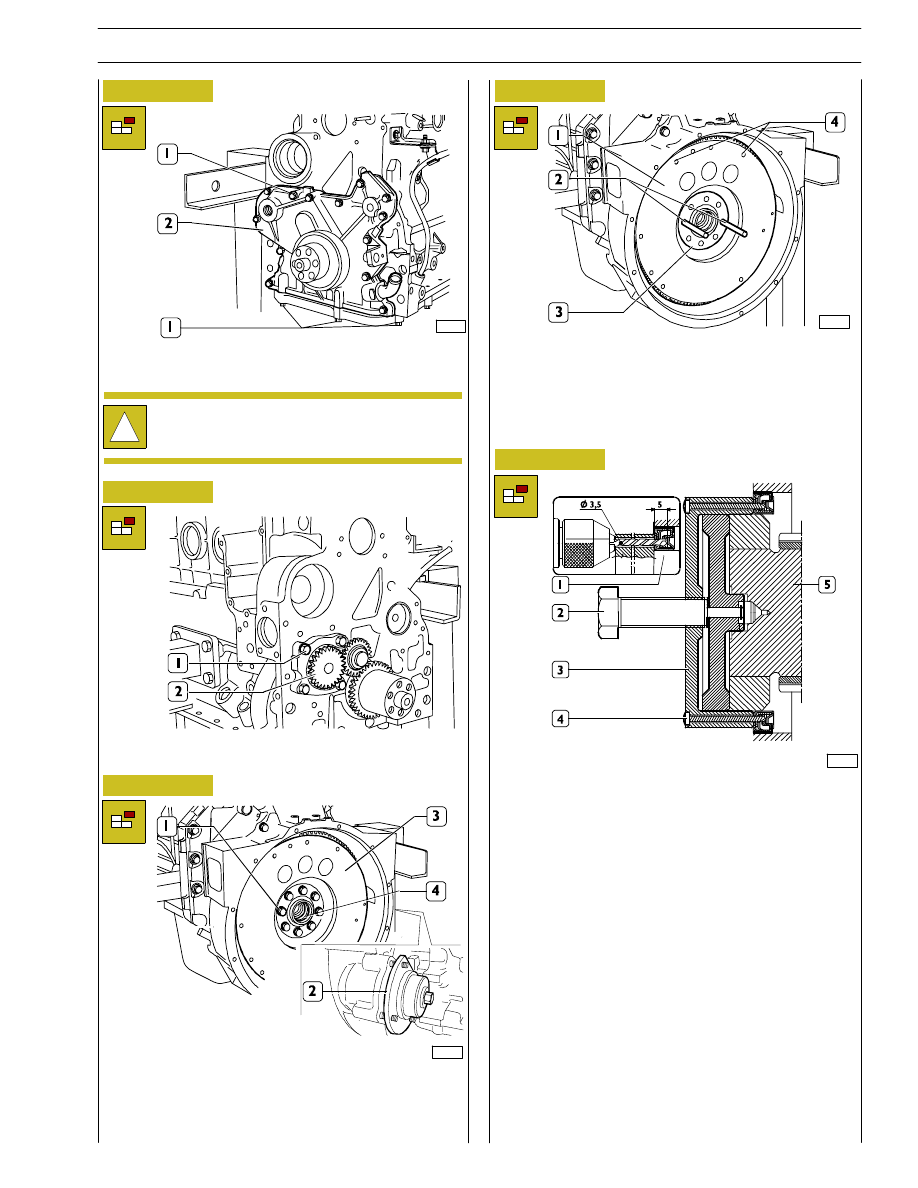
Figure 26
70149
Remove the screws (1) and take out the front cover (2).
!
Take note of screw (1) assembling positions since
they have different lengths.
70151
Remove two opposite screws (1) from the area where the
withdrawal pins will be introduced (2, Figure 29).
Loosen the remaining flywheel fixing screws (3) from the
driving shaft (4).
Remove the flywheel locking tool 99360351.
Figure 27
Remove the screws (1) and disconnect the oil pump (2).
Figure 28
Figure 29
70152
Tighten two screws of medium length into the holes (4) to
sling the flywheel with the hoist.
Throughout the two guide pins (2) previously screw into the
driving shaft holes (3) withdraw the engine flywheel (1) after
slinging it with the hoist.
00903t
Figure 30
Remove the holding ring of the flywheel cover box using the
tool 99340056 (3) to operate on the driving shaft’s back bar
hold (5).
Through the steering holes of the tool, perforate the inside
holding ring with a straight way drill (diam. 3,5mm) for the
depth of 5mm.
Fix the tool 99340056 (3) to the ring tightening the 6 screws
provided with the equipment.(4)
Then proceed removing the ring (1) by tightening the screw
(2).
Using a specific tie rod of the tool 99363204 and an ancillary
lever, remove the external holding ring (2) from the front
cover.
SECTION 3 - DUTY-INDUSTRIAL APPLICATION
15
F4HE NEF ENGINES
Print P2D32N003GB
Base - February 2006
70153
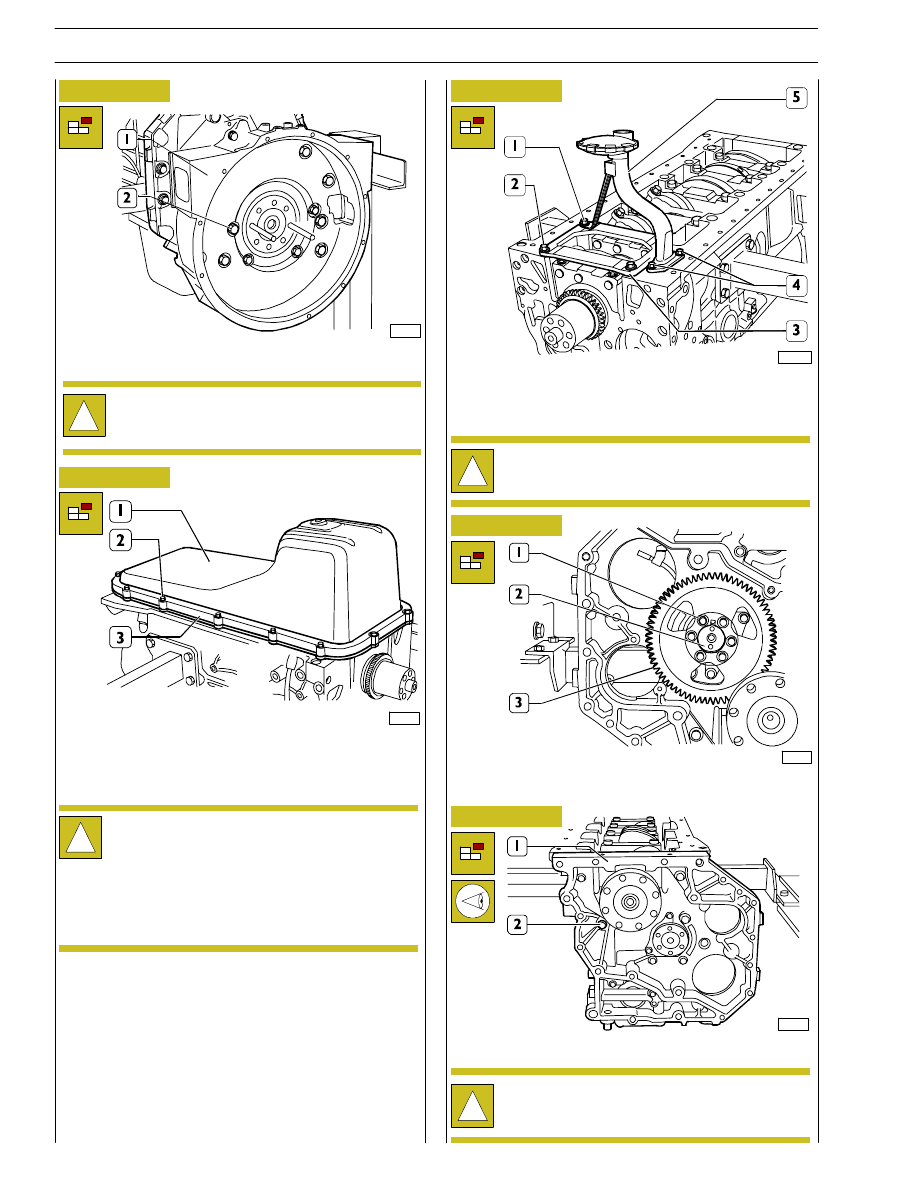
Remove the screws (2) and take out the rear cover (1).
!
Take note of screw (2) assembling positions since
they have different sizes.
74775
Figure 31
Overturn the engine.
Remove the screws (2), disassemble the plate (3) and
disconnect the oil sump (1).
Figure 32
Remove the screws (1 and 4) and disassemble the oil suction
tube (5). Remove the screws (2) and disassemble the
stiffening plate (3).
70156
Figure 33
Remove the screws (1) and remove the gear (3) from the
camshaft (2).
70157
Figure 34
Remove the screws (2) and disconnect the timing gear case
(1).
!
Take note of screw (2) assembling positions since
they have different sizes.
Figure 35
!
The shape and the dimensions of the oil pan and of
the suction tube may vary according to the duty of
the engine. The relevant pictures of the instructions
are
therefore
providing
an
outline
of
the
intervention to be executed.
However the procedures described are still
applicable.
!
For F4HE0684 engines the stiffening plate (4) has a
single element.
86516
16
SECTION 3 - DUTY-INDUSTRIAL APPLICATION
F4HE NEF ENGINES
Base - February 2006
Print P2D32N00GB
Нет комментариевНе стесняйтесь поделиться с нами вашим ценным мнением.
Текст