Engine Iveco C10/C13/C78/Cursor 13/Cursor 78. Manual — part 125
SECTION 2 - APPLICATION G-DRIVE
17
Type
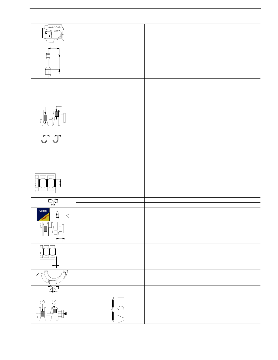
F3B
Type
mm
X
Measuring dimension
X
125
Max. connecting rod
axis misalignment
tolerance
0.08
1
2
∅
∅
1
2
Main journals
∅1
- rated value
- class
1
- class
2
- class
3
Crankpins
∅2
- rated value
- class
1
- class
2
- class
3
99.970 to 100.000
99.970 to 99.979
99.980 to 99.989
99.990 to 100.000
89.970 to 90.000
89.970 to 89.979
89.980 to 89.989
89.990 to 90.000
S 1
S 2
Main bearing shells
S1
Red
Green
Yellow*
3.110 to 3.120
3.121 to 3.130
3.131 to 3.140
Big end bearing shells
S2
Red
Green
Yellow*
1.965 to 1.975
1.976 to 1.985
1.986 to 1.995
3
∅
Main bearing housings
∅3
- rated value
- class
1
- class
2
- class
3
106.300 to 106.330
106.300 to 106.309
106.310 to 106.319
106.320 to 106.330
Bearing shells - main journals
f
0.060
÷ 0.108 * - 0.061 ÷ 0.119 ** - 0.060 ÷ 0.130 ***
Bearing shells - big ends
f
0.050
÷ 0.108 * - 0.051 ÷ 0.109 ** - 0.050 ÷ 0.098 ***
Main bearing shells
0.127 - 2.254 - 0.508
Big end bearing shells
0.127 - 2.254 - 0.508
X1
Main journal,
thrust bearing
X1
47.95 to 48.00
X2
Main bearing housing,
thrust bearing
X2
40.94 to 40.99
X 3
Thrust washer
halves
X3
3.38 to 3.43
Crankshaft end float
0.10 to 0.30
1
2
Alignment
1 - 2
Ovalization
1 - 2
Taper
1 - 2
≤ 0.025
0.010
0.010
*
Fitted in production only and not supplied as spares
f
Spares provided: : * = standard spares - 0.127; ** = 0.254 - 0.508
18
SECTION 2 - APPLICATION G-DRIVE
Type
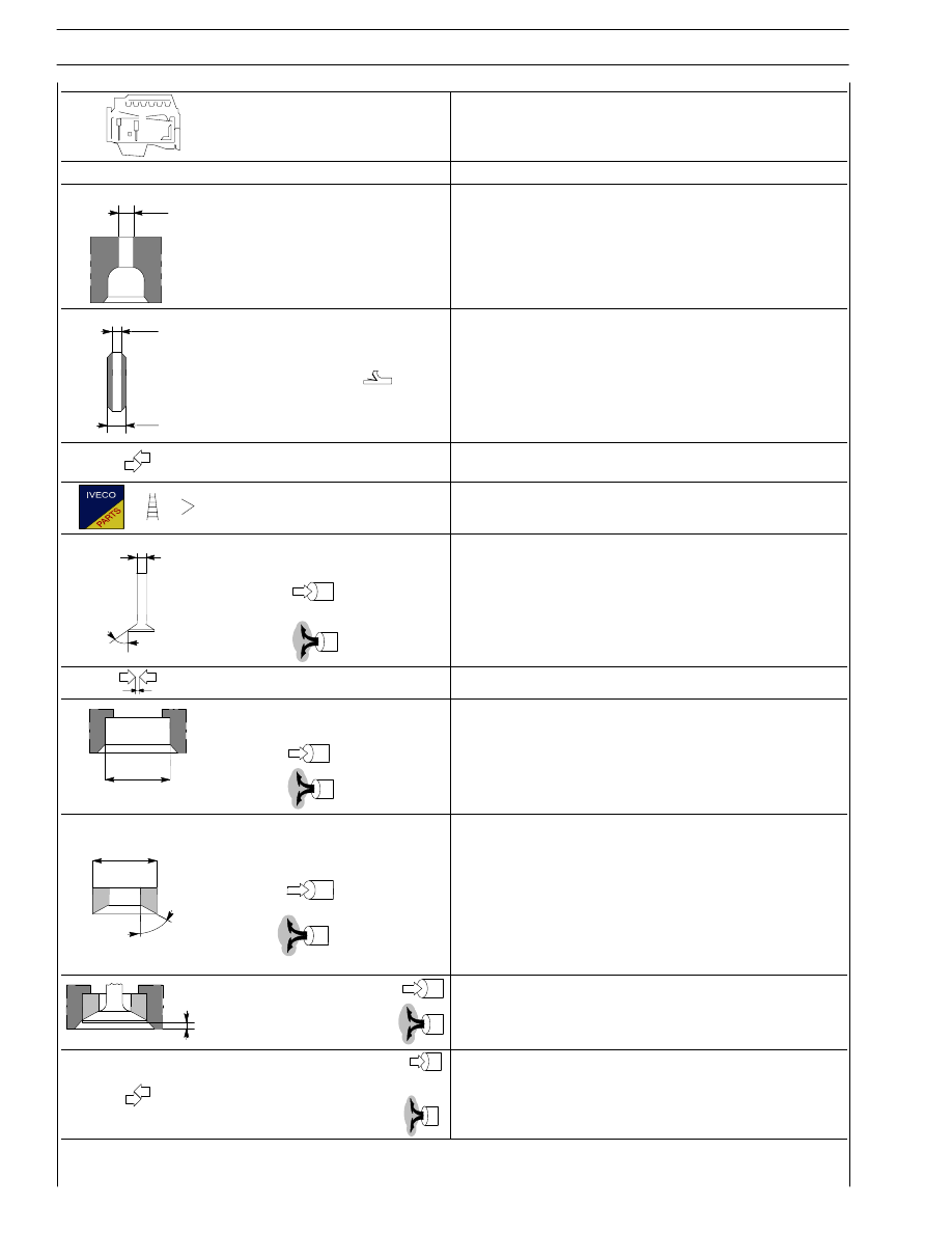
F3B
CYLINDER HEAD - VALVE TRAIN
mm
∅ 1
Valve guide housings
in cylinder head
∅1
15.980 to 15.997
2
∅
Valve guide
∅2
10.015 to 10.030
∅ 3
Valve guide
∅2
∅3
16.012 to 16.025
Valve guides - housings
in the cylinder heads
0.015 to 0.045
Valve guide
0.2 - 0.4
∅ 4
Valves:
∅4
α
9.960 to 9.975
60
° 30′ ± 7′ 30″
α
∅4
α
9.960 to 9.975
45
° 30’ ± 7′ 30″
Valve stem and its guide
0.040 to 0.070
Valve seat in
head
head
∅1
49.185 to 49.220
∅ 1
∅1
∅1
46.985 to 47.020
Outside diameter of valve
2
∅
Outside diameter of valve
seat; angle of valve seat
in cylinder head:
∅2
49.260 to 49.275
∅2
α
60
° - 30’
α
∅2
47.060 to 47.075
∅2
α
45
° - 30′
X
Recessing of valve
0.45 to 0.75
X
Recessing of valve
X
1.65 to 1.95
Between valve
Between valve
seat and head
0.040 to 0.090
0.040 to 0.090
SECTION 2 - APPLICATION G-DRIVE
19
Table 3
Type
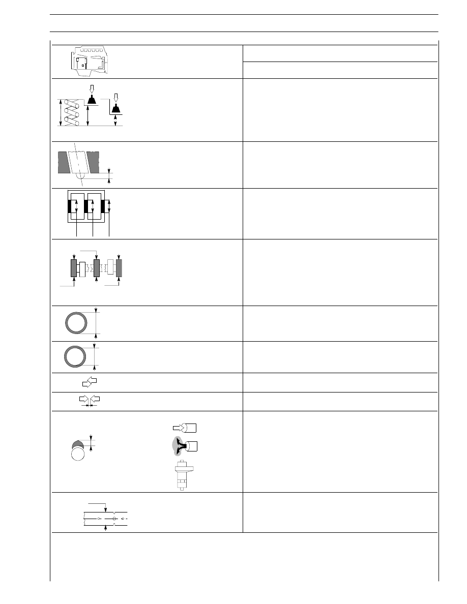
F3B
Type
mm
Valve spring height:
free height
H
73.40
H
H 1
2
under a load of:
H 1
H 2 575 ± 28 N
H1
59
1095
± 54 N
H2
45
X
Injector protrusion
X
0.53 to 1.34
∅
∅
∅
Camshaft bushing housing
in the cylinder head:
1
⇒ 7
Ø
88.000 to 88.030
∅
∅
∅
1
2
3
Camshaft bearing
journals:
1
⇒ 7
Ø
82.950 to 82.968
∅
Outer diameter of
camshaft bushings:
∅
88.153 to 88.183
∅
Inner diameter of
camshaft bushings:
∅
83.018 to 83.085
Bushings and housings
in the cylinder head
0.123 to 0.183
Bushings and bearing
journals
0.050 to 0.135
Cam lift:
9.560
H
9.231
11.216
∅ 1
Rocker shaft
∅1
41.984 to 42.000
20
SECTION 2 - APPLICATION G-DRIVE
Type
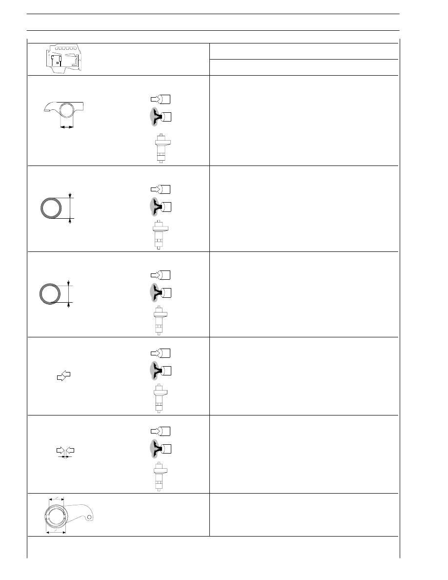
F3B
Type
mm
Seats for bushings in
rocker arms:
45.000 to 45.016
59.000 to 59.019
∅
46.000 to 46.016
Outside diameter of
bushings for rocker arms:
45.090 to 45.130
∅
59.100 to 59.140
46.066 to 46.091
Inside diameter of bushings
for rocker arms:
42.025 to 42.041
∅
56.030 to 56.049
42.015 to 42.071
Bushings and seats:
0.074 to 0.130
0.081 to 0.140
0.050 to 0.091
Rocker arm bushings and shaft:
0.025 to 0.057
0.025 to 0.057
0.015 to 0.087
O1
O2
Engine brake control lever
Eccentric pin outer
diameter
∅1
Rocker arms shaft seat
∅2
55.981 to 56.000
42.025 to 42.041
Нет комментариевНе стесняйтесь поделиться с нами вашим ценным мнением.
Текст