Engine Iveco C10/C13/C78/Cursor 13/Cursor 78. Manual — part 110

70000
99375
87051
86290
MAIN DATA TO CONTROL EXHAUST AND
DISCHARGE VALVE SPRING
- fit springs (6) and the upper plate (5);
- apply tool 99360263 (2) and block it with bracket (4);
tighten the lever (1) until cotters are installed (3),
remove tool (2).
VALVE SPRINGS
Fitting the valves and oil seal ring
Free spring height
Valve closed
Valve open
71724
To insert bushing (7), proceed as follows:
- Unscrew the grip (I) and the extension (N).
- Refit the guide (G) from the inside as shown in the figure.
- Position the bushing on the drift (A) and bring it close
up to the seat, making the bushing hole match the
lubrication hole in the head. Drive it home.
The 7
th
bushing is driven in when the reference mark (C)
is flush with the bushing seat.
Before assembly, the flexibility of the valve springs has to be
checked with the tool 99305047.
Compare the load and elastic deformation data with those
of the new springs given in the following figure.
Rear
Figure 98
Figure 99
Figure 100
Figure 101
Figure 102
Lubricate the valve stem and insert the valves in the
respective valve guides; fit the lower caps (1). Use tool
99360329 to fit the oil seal (2) on the valve guides (3) of the
exhaust valves; then, to fit the valves, proceed as follows.
Should valves not have been overhauled or
replaced, remount them according to numbering
performed on dismounting.
NOTE
SECTION 4 - OVERHAUL AND TECHNICAL SPECIFICATIONS
45
99281
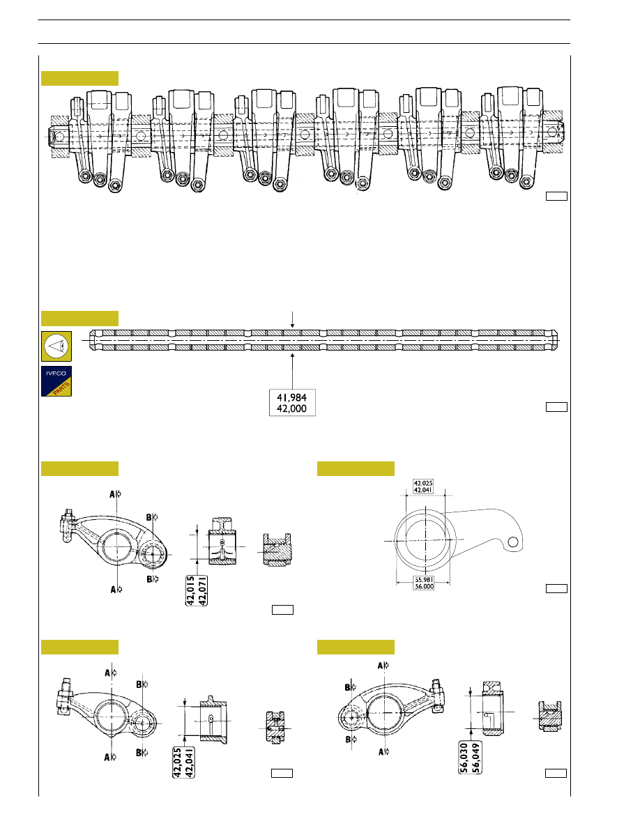
The camshaft cams directly control rockers: 6 for injectors and 12 for valves.
Rockers slide directly on the cam profiles via rollers.
The other end acts on a bar directly supported by the two valves stems.
A pad is placed between the rocker adjusting screw and the bar.
Two lubrication holes are obtained inside the rockers.
The rocker shaft practically covers the whole cylinder head; remove it to have access to all the underlying components.
Figure 103
71728
71729
71730
Figure 104
Figure 105
Figure 106
PUMP INJECTOR ROCKER
EXHAUST VALVES ROCKER
The bush surfaces must not show any trace of scoring of
excessive wear; otherwise, replace bushes or the whole
rocker.
DISCHARGE VALVE ROCKER
Rocker
SECTION A-A
SECTION B-B
SECTION A-A
SECTION B-B
SECTION A-A
SECTION
B-B
Check that the surface of the shaft shows no scoring or signs of seizure; if it does, replace it.
MAIN DATA OF THE ROCKER ARM SHAFT
73557
Shaft
Figure 107
Figure 108
99376
ROCKER SHAFT
46
SECTION 4 - OVERHAUL AND TECHNICAL SPECIFICATIONS

TIMING CONTROL COMPONENT PARTS
1. Camshaft - 2. Bushing - 3. Pin - 4. Articulated rod -
5. Camshaft control gear - 6. Idler gear - 7. Twin idler gear
- 8. Drive shaft driving gear.
86925
*
This measurement is obtained after assembling.
TIMING GEAR
Camshaft drive
101602
Figure 109
Figure 110
Figure 111
101601
*
This measurement is obtained after assembling.
Idler gear pin
Idler gear
Twin intermediate gear pin
Twin idler gear
Replacing the bushings
Bushings (2) can be replaced when they are worn. Put up the
bushing, then bore it to obtain the diameter shown on
Figure 110 or Figure 111.
The bushing must be driven into the gear by
following the direction of the arrow and setting the
latter to the dimension shown on Figure 110 or
Figure 111.
Rated assembling play between gear bushings and pins:
Figure 110 — 0.045
÷ 0.075 mm
Figure 111 — 0.045
÷ 0.085 mm.
NOTE
SECTION 4 - OVERHAUL AND TECHNICAL SPECIFICATIONS
47
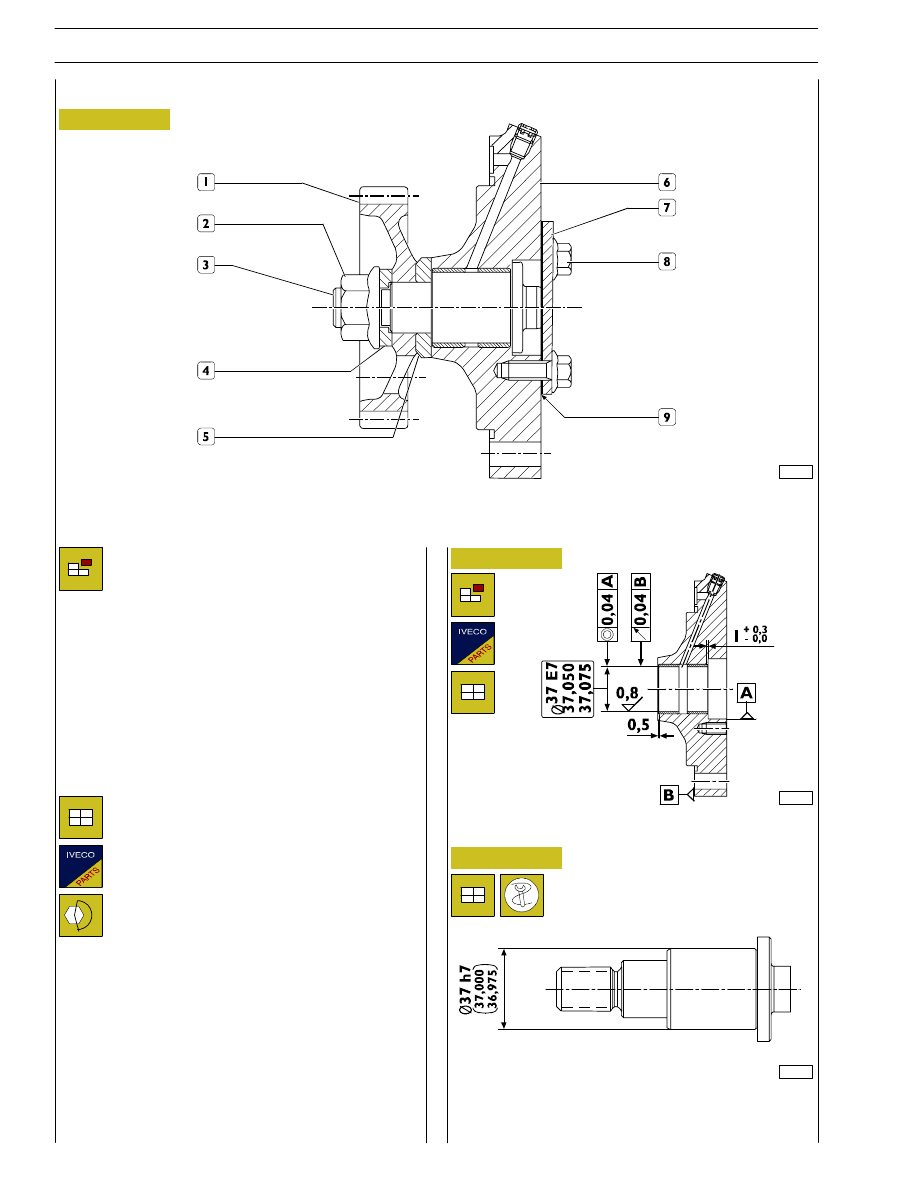
Rated shaft/rear power takeoff supporting bushing backlash
: 0,05
÷ 0,10 mm.
Remove retaining screws (8) and disconnect cover (7) with
seal (9) from support (6).
Lock shaft (3) rotation and remove nut (2) .
Remove from shaft (3): washer (4), gear (1) and spacer (5).
Remove shaft (3) from support (6).
Figure 112
Figure 113
Figure 114
REAR POWER TAKEOFF
107991
1. Gear - 2. Nut - 3. Shaft - 4. Washer - 5. Spacer - 6. Support - 7. Cover - 8. Screw - 9. Seal.
Removal
Refitting
For refitting, reverse operations described for
removal according to instructions below:
- install a new seal (9);
- lubricare shaft shank (3) with engine oil;
- lock screws and nut at prescribed torque.
107992
Shaft
107993
48
SECTION 4 - OVERHAUL AND TECHNICAL SPECIFICATIONS
Нет комментариевНе стесняйтесь поделиться с нами вашим ценным мнением.
Текст