Engine Iveco C10/C13/C78/Cursor 13/Cursor 78. Manual — part 109
60624
47585
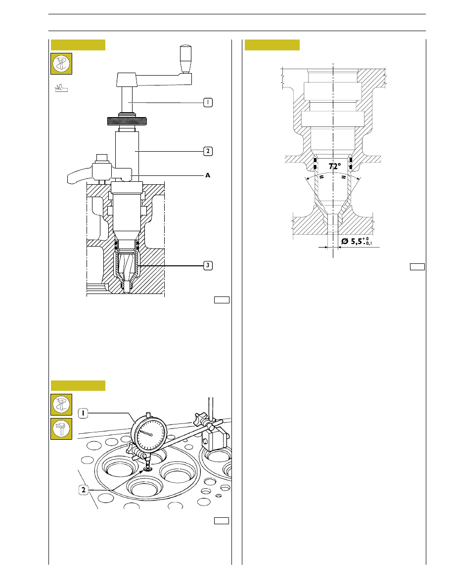
Check injector protrusion (2) with the dial gauge (1).
The protrusion must be 0.52 - 1.34 mm.
Checking injector protrusion
71720
INJECTOR CASE ASSEMBLY DIAGRAM
Figure 86
- Using the milling cutter 99394043 (1-2), regrind the
injector seat in the case (3).
Figure 87
Figure 88
SECTION 4 - OVERHAUL AND TECHNICAL SPECIFICATIONS
41

47506
47505
47507
Figure 89
Figure 90
Figure 91
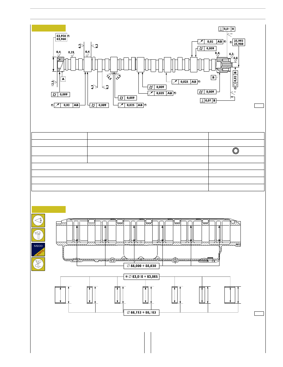
Camshaft
Checking cam lift and pin alignment
When the camshaft (4) is on the tailstock (1), check alignment of supporting pin (3) using a centesimal gauge (2); it must not
exceed 0.030 mm. If misalignment exceeds this value, replace the shaft.
In order to check installation clearance, measure bush inner diameter and camshaft pin (1) diameter; the real clearance is obtained
by their difference.
If clearance exceeds 0.135 mm, replace bushes and, if necessary, the camshaft.
Place the camshaft (4) on the tailstock (1) and check cam lift (3) using a centesimal gauge (2); values are shown in table on page
9.
1
42
SECTION 4 - OVERHAUL AND TECHNICAL SPECIFICATIONS
The surface of the bushings must show no sign of seizing or
scoring; replace them if they do.
Measure the inside diameter of the bushings with a bore
gauge.
60626
60627
Figure 92
Figure 93
MAIN DATA OF THE CAMSHAFT AND TOLERANCES
The surfaces of the supporting pins of the shaft and those of the cams need to be extra smooth.
Whereas, if they show any signs of seizing or scoring, you should replace the shaft and the relevant bushings.
MAIN DATA OF THE BUSHINGS FOR THE CAMSHAFT AND SEATS ON THE CYLINDER HEAD
* Bushing inside diameter after driving in
Bushings
If you find a higher value than the tolerance, replace them.
To remove and fit the bushings, use the appropriate drift
99360499.
SECTION 4 - OVERHAUL AND TECHNICAL SPECIFICATIONS
43
TOLERANCES
FEATURE SUBJECT OF TOLERANCE
SYMBOL
DIRECTION
Perpendicularity
⊥
POSITION
Concentricity or coaxiality
SWING
Circular oscillation
↗
CLASS OF IMPORTANT ASCRIBED TO PRODUCT CHARACTERISTICS
SYMBOL
CRITICAL
©
IMPORTANT
⊕
SECONDARY
⊝
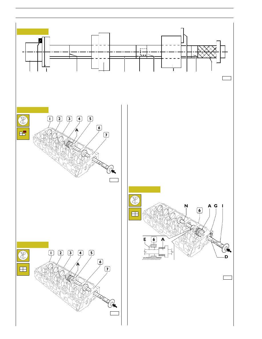
Figure 94
71721
A B C
D
E
F
D
L
G
H D
I
A. Drift with seat for bushings to insert/extract. - B. Grub screw for positioning bushings. - C. Reference mark to insert
seventh bushing correctly. - D. Reference mark to insert bushings 1, 2, 3, 4, 5, 6 correctly (red marks). - E. Guide bushing. -
F. Guide line. - G. Guide bushing to secure to the seventh bushing mount. - H. Plate fixing yellow bushing to cylinder head.
- I. Grip. - L. Extension coupling.
Figure 95
The sequence for removing the bushings is 7, 6, 5, 4, 3, 2, 1.
The bushings are extracted from the front of the single seats.
Removal does not require the drift extension for bushings 5,
6 and 7 and it is not necessary to use the guide bushing.
For bushings 1, 2, 3 and 4 it is necessary to use the extension
and the guide bushings.
Position the drift accurately during the phase of removal.
Removal
Figure 96
Assembly
1 Position the bushing to insert on the drift (A) making the
grub screw on it coincide with the seat (B) (Figure 94) on
the bushing.
2 Position the guide bushing (E) and secure the guide
bushing (G) (Figure 94) on the seat of the 7
th
bushing
with the plate (H).
3 While driving in the bushing, make the reference mark (F)
match the mark (M). In this way, when it is driven home,
the lubrication hole on the bushing will coincide with the
oil pipe in its seat.
The bushing is driven home when the 1
st
red reference
mark (D) is flush with the guide bushing (G).
Assemble the drift together with the extension.
To insert bushings 1, 2, 3, 4 and 5, proceed as follows:
71723
Figure 97
To insert the bushing (6), proceed as follows:
- Unscrew the grip (I) and the extension (N).
- Position the extension (N) and the guide bushing (E) as
shown in the figure.
- Repeat steps 1, 2, 3.
Rear
Rear
77795
71725
Replacing camshaft bushes using beater 99360499
44
SECTION 4 - OVERHAUL AND TECHNICAL SPECIFICATIONS
Нет комментариевНе стесняйтесь поделиться с нами вашим ценным мнением.
Текст