Engine Iveco C10/C13/C78/Cursor 13/Cursor 78. Manual — part 24
47577
77812
16798
35012
Figure 13
Figure 14
Figure 15
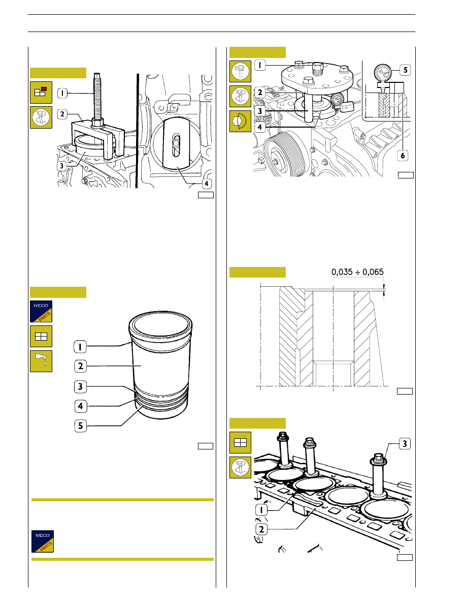
Place details 99360706 (1 and 2) and plate 99360724 (4) as
shown in the figure, by making sure that the plate (4) is
properly placed on the cylinder liners.
Tighten the screw nut (1) and remove the cylinder liner (3)
from the block.
Always replace water sealing rings (3, 4 and 5).
Install the adjustment ring (1) on the cylinder liner (2);
lubricate lower part of liner and install it in the cylinder unit
using the proper tool.
Check cylinder barrel protrusion with tool 99360334
(1-2-3-4) and tighten screw (1) to 170 Nm.
With dial gauge 99395603 (5) placed on base 99370415 (6).
Measure the cylinder barrel protrusion compared to the
cylinder head supporting plane, it must be 0.035 to 0.065 mm
(Figure 16); otherwise replace the adjusting ring (1,
Figure 14) fitted with spare parts having different thickness.
When the installation is completed, block the cylinder liners
(1) to the block (2) with studs 99360703 (3).
Fitting and checking protrusion
(Demonstration)
Figure 16
CYLINDER LINER PROTRUSION
49017
The adjustment ring (1) is supplied as spare parts in
the following thicknesses: 0.08 mm - 0.10 mm - 0.12
mm.
Figure 17
Replacing cylinder liners
Removal
NOTE
14
SECTION 4 - OVERHAUL AND TECHNICAL SPECIFICATIONS
49018
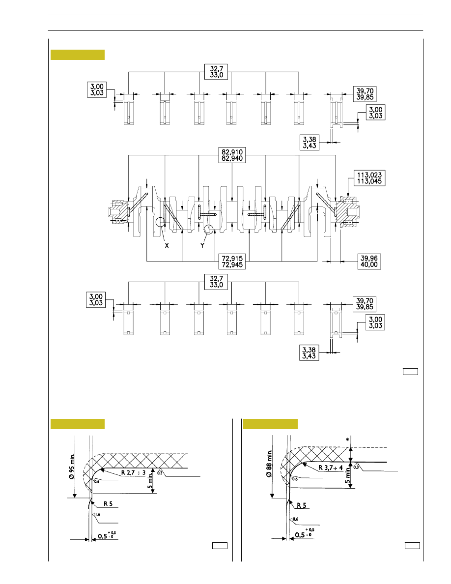
Figure 18
Figure 19
X
. Detail of main journals connections
Y.
Detail of crank pins connections
Figure 20
MAIN DATA FOR THE CRANK SHAFT PINS AND THE HALF BEARINGS
Check the condition of the journals and the big end pins; there must no be signs of scoring, ovalization or excessive wear.
The data given refer to the normal diameter of the pins.
47537
47538
Upper main journal half bearing
Lower main journal half bearings
BUFF
BUFF
CRANKSHAFT
SECTION 4 - OVERHAUL AND TECHNICAL SPECIFICATIONS
15
MEASURING CRANK PINS
During grinding, pay attention to journal and crank pins values
specified in figures 19 and 20.
47535
47536
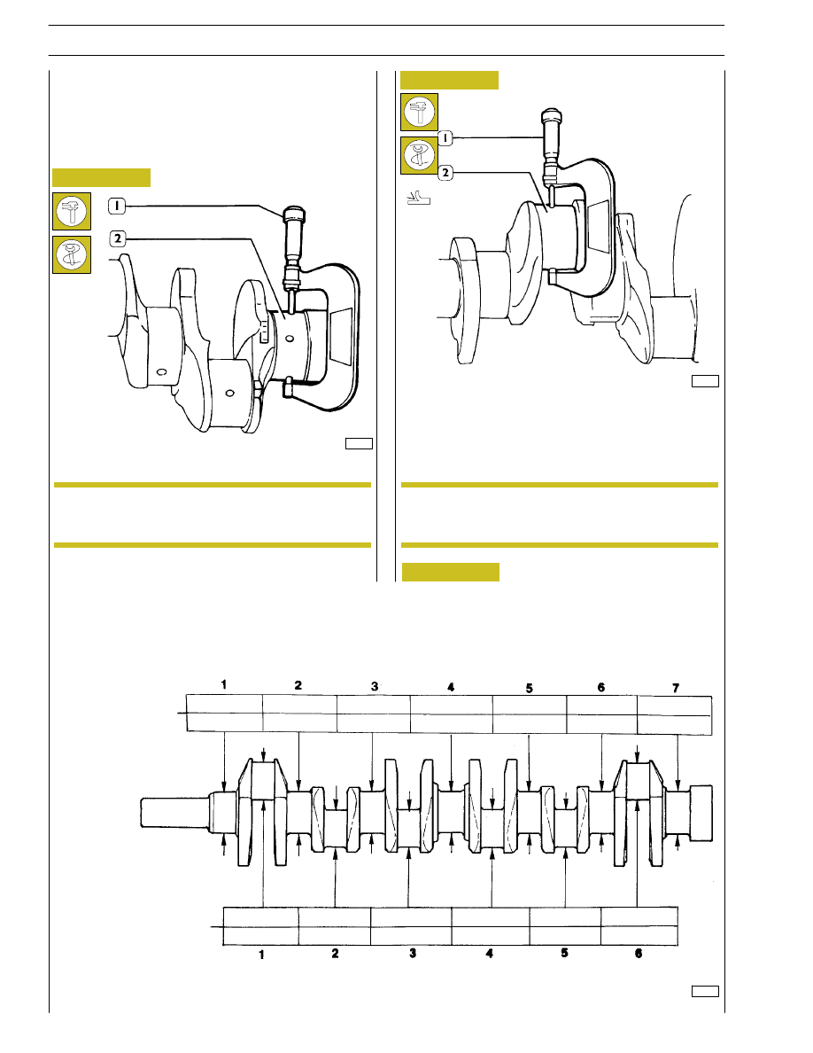
Figure 21
Figure 22
MEASURING THE MAIN JOURNALS
Measuring main journals and crank pins
Before grinding the crank pins using a micrometer (1),
measure the main journals and the crank pins (2) and decide,
on the basis of the undersizing of the bearings, the final
diameter to which the pins are to be ground.
It is advisable to enter the values found in a table
(Figure 23).
All journals and crank pins must also be ground to
the same undersizing class, in order to avoid any
alteration to shaft balance.
Figure 23
Fill in this table with the measurements of the main journals and the crank pins.
MAIN JOURNALS
36061
Ø MIN.
Ø MAX.
Ø MIN.
Ø MAX.
CRANK PINS
NOTE
NOTE
16
SECTION 4 - OVERHAUL AND TECHNICAL SPECIFICATIONS
For each of the journals of the crankshaft, it is necessary to carry out the following operations:
MAIN JOURNALS:
- Determine the class of diameter of the seat in the
crankcase.
- Determine the class of diameter of the main journal.
- Select the class of the bearing shells to mount.
CRANKPINS:
- Determine the class of diameter of the seat in the
connecting rod.
- Determine the class of diameter of the crankpin.
- Select the class of the bearing shells to mount.
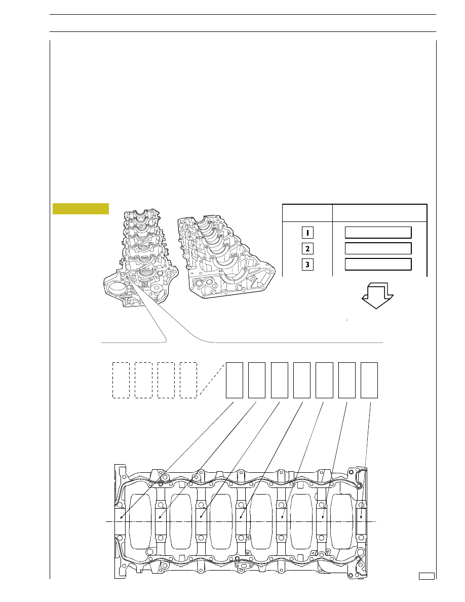
DEFINING THE CLASS OF DIAMETER OF THE SEATS FOR BEARING SHELLS ON THE CRANKCASE
On the front of the crankcase, two sets of numbers are marked in the position shown (Figure 24 at top).
- The first set of digits (four) is the coupling number of the crankcase with its base.
- The following seven digits, taken singly, are the class of diameter of each of the seats referred to (Figure 24 at bottom).
- Each of these digits may be 1, 2 or 3.
47535
89.000 to 89.009
89.010 to 89.019
89.020 to 89.030
Figure 24
CLASS
MAIN BEARING HOUSING
NOMINAL DIAMETER
PRELIMINARY MEASUREMENT OF MAIN AND BIG END BEARING SHELL SELECTION DATA
SECTION 4 - OVERHAUL AND TECHNICAL SPECIFICATIONS
17
Нет комментариевНе стесняйтесь поделиться с нами вашим ценным мнением.
Текст