Engine Iveco C10/C13/C78/Cursor 13/Cursor 78. Manual — part 23
10
SECTION 4 - OVERHAUL AND TECHNICAL SPECIFICATIONS
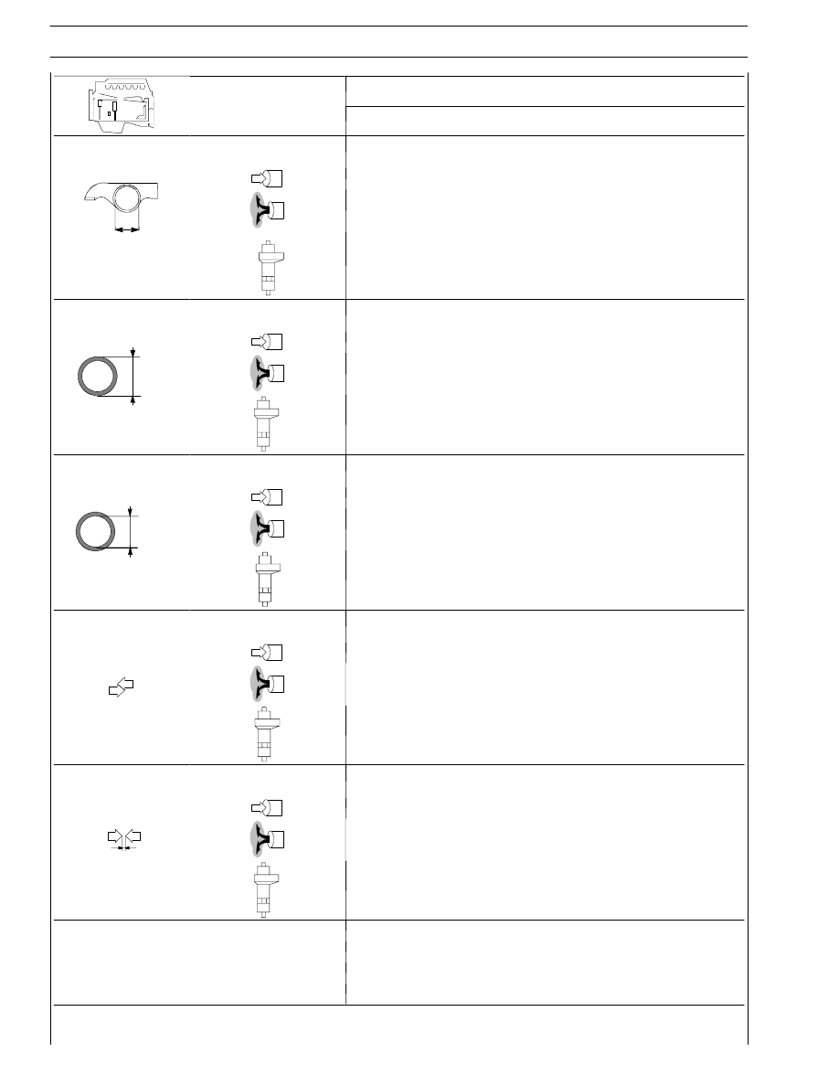
Type
F2B
mm
Bushing housing in rocker
arms
41.000 to 41.016
41.000 to 41.016
∅
42.000 to 42.016
Bushing outer diameter
for rocker arms:
41.097 to 41.135
∅
41.097 to 41.135
42.066 to 42.091
Bushing inner diameter
for rocker arms:
38.025 to 38.041
∅
38.025 to 38.041
38.015 to 38.071
Between
bushings
and
housings
0.081 to 0.135
0.081 to 0.135
0.050 to 0.091
Between rocker arms and
shaft
0.025 to 0.057
0.225 to 0.057
0.015 to 0.087
TURBOCHARGER
Type
HOLSET HX40W
End float
0.025 to 0.127
Radial play
0.254 to 0.356
47576
47571
47570
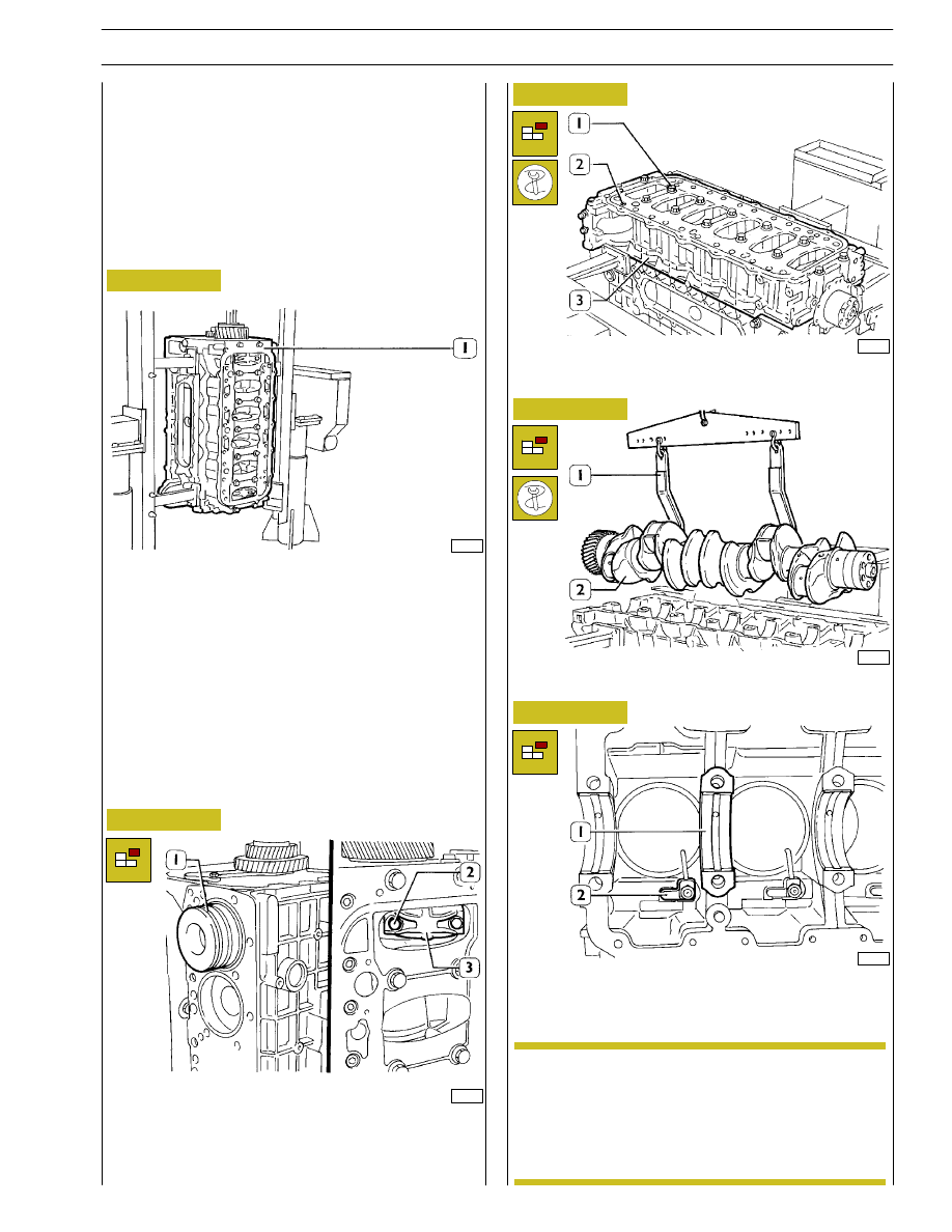
By means of proper and splined wrenches, untighten the
screws (1) and (2) and remove the under-block (3).
Remove the crankshaft (2) with tool 99360500 (1).
Remove the crankshaft half-bearings (1), untighten the
screws and remove oil spray nozzles (2).
Take down cylinder liners as specified in the relative
paragraph on page 14.
After disassembling the engine, thoroughly clean
disassembled parts and check their integrity.
Instructions for main checks and measures are
given in the following pages, in order to determine
whether the parts can be re-used.
Untighten screws (2) fixing the connecting rod cap (3) and
remove it. Remove the connecting rod-piston assembly from
the upper side. Repeat these operations for the other pistons.
Figure 1
Figure 2
Figure 3
Figure 4
Figure 5
Rotate the block (1) to the vertical position.
47575
47574
ENGINE OVERHAUL
ENGINE REMOVAL AT THE BENCH
The
following
instructions
are
prescribed
on
the
understanding that the engine has previously been placed on
the rotating bench and that removal of all specific
components of the equipment have been already removed
as well. (See Section 3 of the manual herein).
The section illustrates therefore all the most important
engine overhaul procedures.
NOTE
SECTION 4 - OVERHAUL AND TECHNICAL SPECIFICATIONS
11
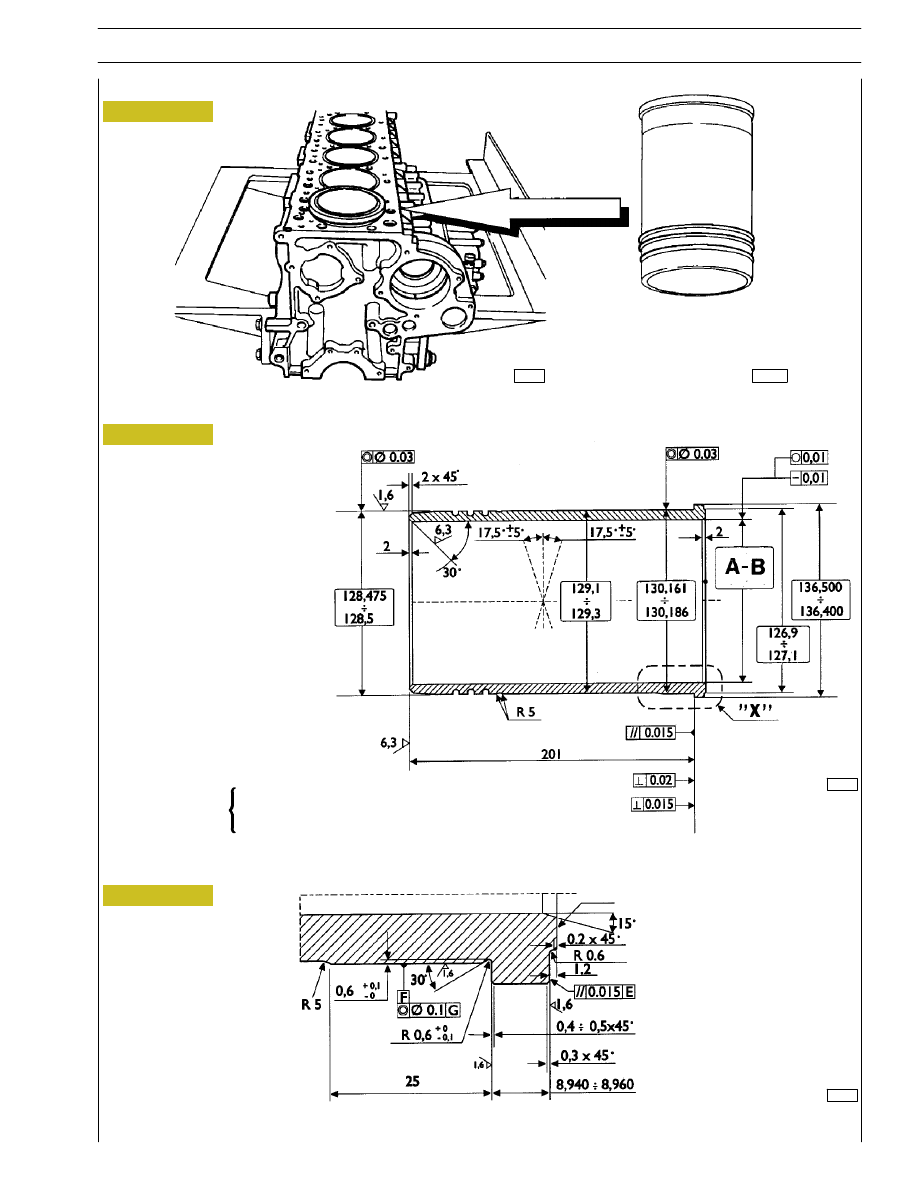
A = Selection class Ø 115 to 115.012 mm
B = Selection class Ø 115.010 to 115.022 mm
In case of maximum wear max 0.150 mm or maximum
ovalization max 0.100 mm compared to the values indicated
in the figure, the liners must be replaced as they cannot be
ground, lapped or trued.
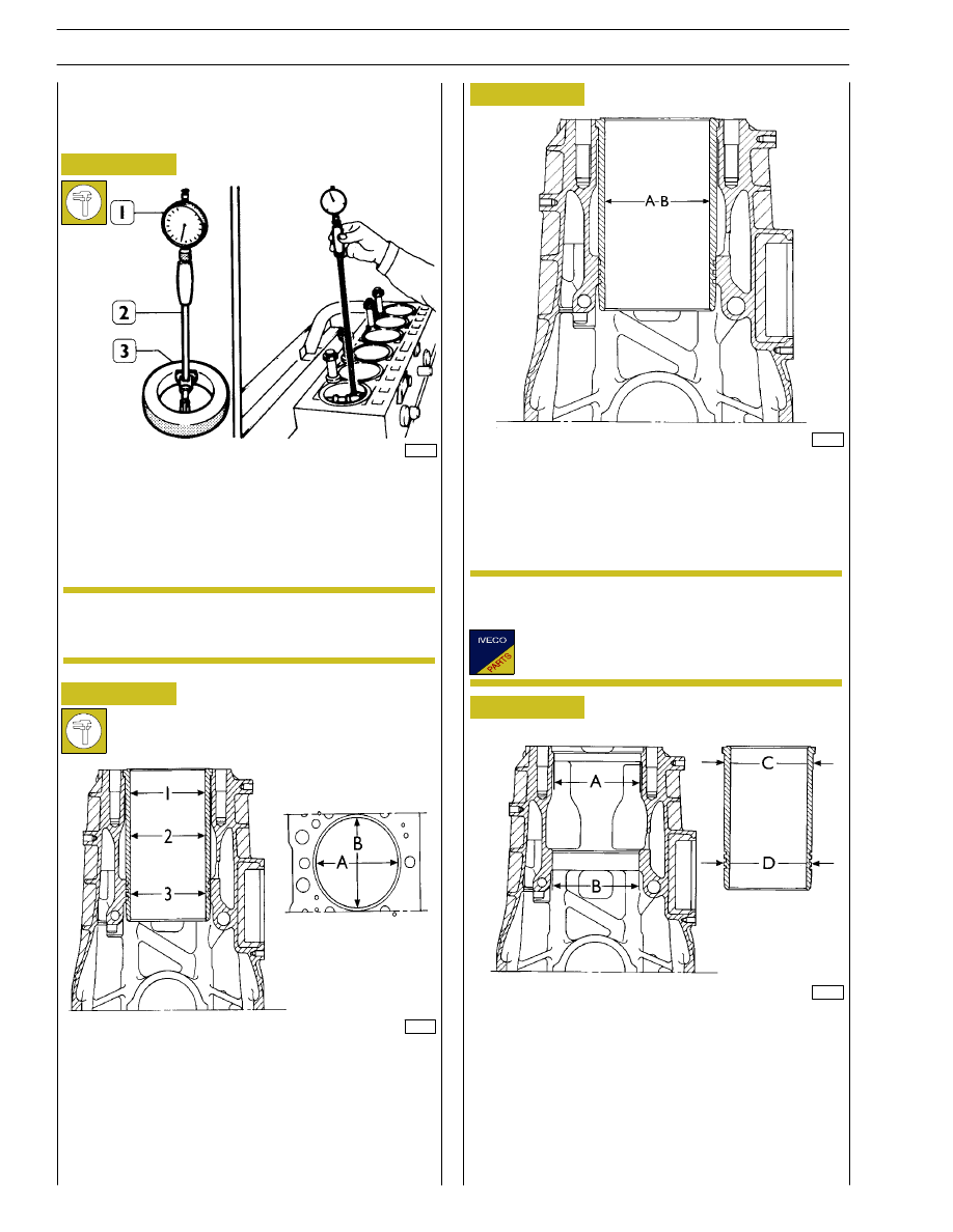
REPAIR OPERATIONS
CYLINDER BLOCK
Checks and measurements
Internal diameter of the cylinder liners is checked for
ovalization, taper and wear, using a bore dial (1) centesimal
gauge 99395687 (2) previously reset to ring gauge (3),
diameter 115 mm.
If a 115 ring gauge is not available use a micrometer
caliper.
A = Ø 130.200 to 130.225 mm
B = Ø 128.510 to 128.535 mm
C = Ø 130.161 to 130.186
D = Ø 128.475 to 128.500 mm
The figure shows the outer diameters of the cylinder liners
and the relative seat inner diameters.
The cylinder liners can be extracted and installed several
times in different seats, if necessary.
34994
47439
47440
47441
Figure 6
Figure 7
Figure 8
Figure 9
1 = 1st measuring
2 = 2nd measuring
3 = 3rd measuring
Carry out measurings on each cylinder liner at three different
levels and on two (A-B) surfaces, to one another
perpendicular, as shown in Figure 7.
(Demonstration)
Cylinder liners are equipped with spare parts with
“A“ selection class.
NOTE
NOTE
12
SECTION 4 - OVERHAUL AND TECHNICAL SPECIFICATIONS
45150
99278
47533
Figure 10
Figure 11
CYLINDER LINERS MAIN DATA
DETAIL “X”
“A“ = Selection class marking area
Figure 12
47534
BLOCK WITH CYLINDER LINERS
A 115.000 to 115.012 mm
B 115.010 to 115.022 mm
Selection class
A
CYLINDER LINERS
SECTION 4 - OVERHAUL AND TECHNICAL SPECIFICATIONS
13
Нет комментариевНе стесняйтесь поделиться с нами вашим ценным мнением.
Текст