Engine Iveco C10/C13/C78/Cursor 13/Cursor 78. Manual — part 86

Figure 5
Figure 6
-
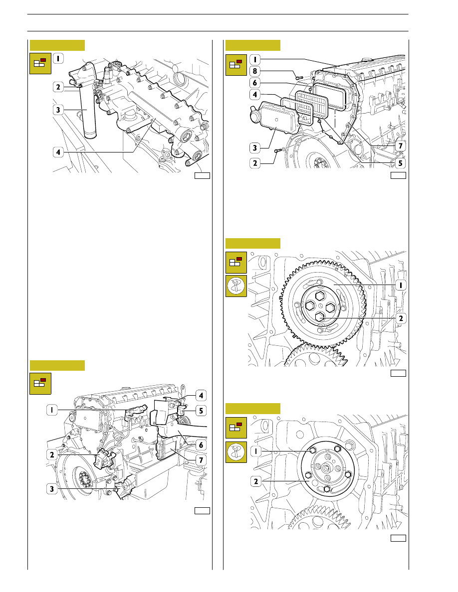
Using a suitable tool (3), work in the direction of the arrow
on the tightener (2) and remove the belt (1).
99359
Remove:
-
alternator (2).
-
supports (1 and 3).
99360
Figure 7
99256
Remove:
-
thermostat assembly (8);
-
pipes complete with coolant (6);
-
pulley (4);
-
water pump (7);
-
automatic tightener support (1);
-
fixed tightener (5);
-
damper flywheel (3) and pulley beneath;
-
automatic tightener (2);
Figure 8
With the extractor 99340053 (2) applied as shown in the
figure, extract the seal (4). Undo the screws (3) and take off
the cover (1). Disconnect all the electrical connections and
sensors.
99361
8
SECTION 3 - INDUSTRIAL APPLICATION
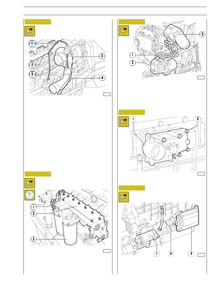
Using tool 99360314 unscrew the oil filters (3).
Remove fastening screws (1) and disassemble heat exchanger
(2).
Disconnect the fuel pipes (1) from the fuel pump (2).
Remove:
-
the fuel pump (2);
-
fuel filter (3) and fuel pipes (1).
Take out the screws (2) and remove the intake manifold (1).
Remove:
-
the starter motor (1);
-
the control unit (2) and its support;
-
the oil dipstick (3) from the crankcase.
Figure 9
Figure 10
Figure 11
Figure 12
99263
99273
99264
On the engine exhaust side, remove the following parts:
-
oil delivery pipe (1);
-
actuator air pipe (5);
-
oil return pipe (4);
-
turbocharger (3);
-
exhaust manifold (2).
99274
Figure 13
101605
SECTION 3 - INDUSTRIAL APPLICATION
9
60494
60493
85480
60496
60497
-
Unscrew the screws (1) and remove the heat exchanger (4);
-
unscrew the screws (2) and remove the water line (3).
Disassemble the following parts: fuel filter support (1); fuel
pump (2); engine start button support (4); PWN valve air filter
(5); inlet manifold (6) complete with engine pre-heating
resistor.
-
Unscrew the screws (2) and remove the gear (1) fitted
with phonic wheel.
-
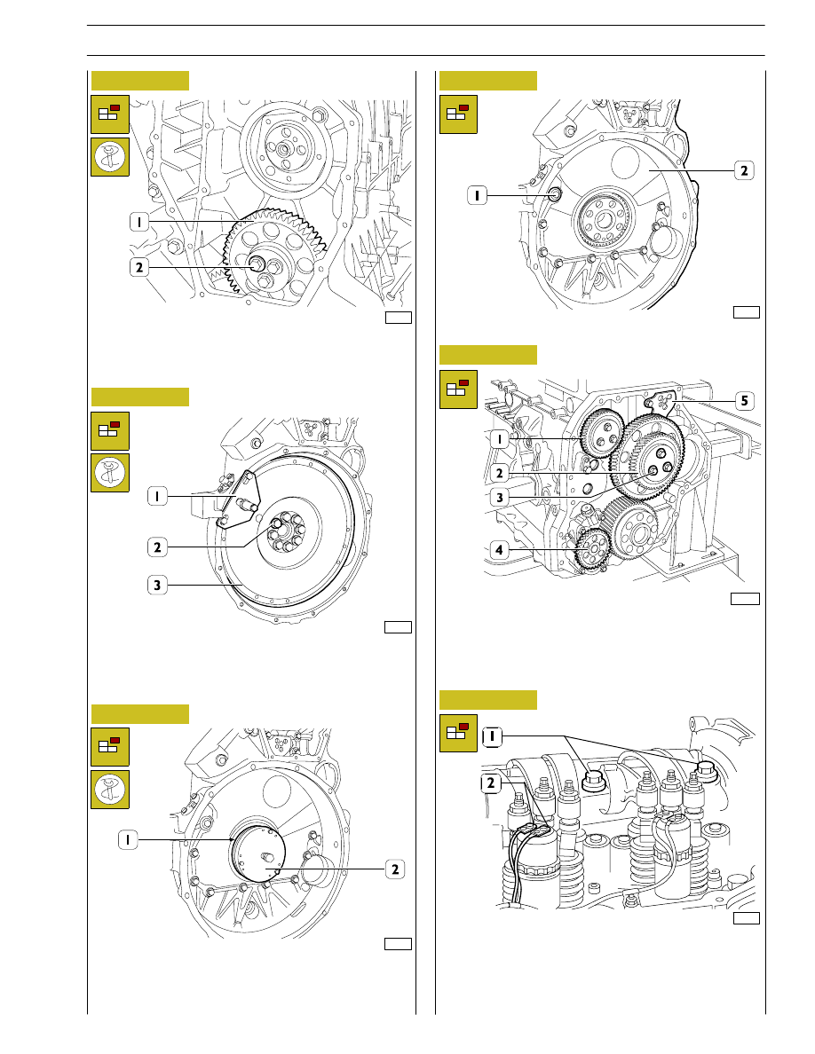
Unscrew the screws (1); tighten one screw in a reaction
hole and remove the shoulder plate (2), remove the sheet
gasket.
Figure 14
Figure 15
Figure 16
Figure 17
Remove the rocker arm cover (1), take off the screws (2) and
remove: the cover (3), the filter (5) and the gaskets (4 and 6).
Take off the screws (8) and remove the blow-by case (7).
Figure 18
10
SECTION 3 - INDUSTRIAL APPLICATION
60498
60500
60499
60501
99365
Figure 19
Figure 20
Figure 21
Figure 22
Figure 23
Unscrew the screws (2) and remove the transmission gear (1).
Stop the engine flywheel (3) rotation by means of tool
99360351 (1), unscrew the fixing screws (2) and remove the
engine flywheel (3).
Apply the extractor 99340054 (2) and pull out the seal
gasket (1).
Unscrew the screws (1) and take down the gearbox (2).
- To release lever stop springs.
- Loosen the screws, then remove electric connections (1)
from the pump injector solenoid valves.
- Unscrew the screws (2) fixing the rocker arm shaft.
Figure 24
106219
Remove screws (3) and dismount double gear (2).
Remove securing screw and dismount articulated rod (5).
Dismount oil pump (4).
SECTION 3 - INDUSTRIAL APPLICATION
11
Нет комментариевНе стесняйтесь поделиться с нами вашим ценным мнением.
Текст