Engine Iveco C10/C13/C78/Cursor 13/Cursor 78. Manual — part 72

71723
71724
Figure 99
Figure 100
To insert the bushing (6), proceed as follows:
- Unscrew the grip (I) and the extension (N).
- Position the extension (N) and the guide bushing (E) as
shown in the figure.
- Repeat steps 1, 2, 3.
To insert bushing (7), proceed as follows:
- Unscrew the grip (I) and the extension (N).
- Refit the guide (G) from the inside as shown in the figure.
- Position the bushing on the drift (A) and bring it close
up to the seat, making the bushing hole match the
lubrication hole in the head. Drive it home.
The 7
th
bushing is driven in when the reference mark (C)
is flush with the bushing seat.
Front
Rear
Front
Rear
70000
Figure 101
Figure 102
MAIN DATA TO CHECK THE SPRING
FOR INTAKE AND EXHAUST VALVES
Valve springs
Before assembly, the flexibility of the valve springs has to be
checked with the tool 99305047.
Compare the load and elastic deformation data with those
of the new springs given in the following figure.
Free spring height
Valve closed
Valve open
106222
46
SECTION 4 - OVERHAUL AND TECHNICAL SPECIFICATIONS

44925
The cams of the camshaft control the rocker arms directly: 6 for the injectors and 12 for the valves.
The rocker arms run directly on the profiles of the cams by means of rollers.
The other end acts on a crosspiece that rests on the stem of the two valves.
There is a pad between the rocker arm adjustment screw and the crosspiece.
There are two lubrication ducts inside the rocker arms.
The length of the rocker arm shaft is basically the same as that of the cylinder head. It has to be detached to be able to reach
all the parts beneath.
Figure 103
Fitting valves and oil seal
Figure 104
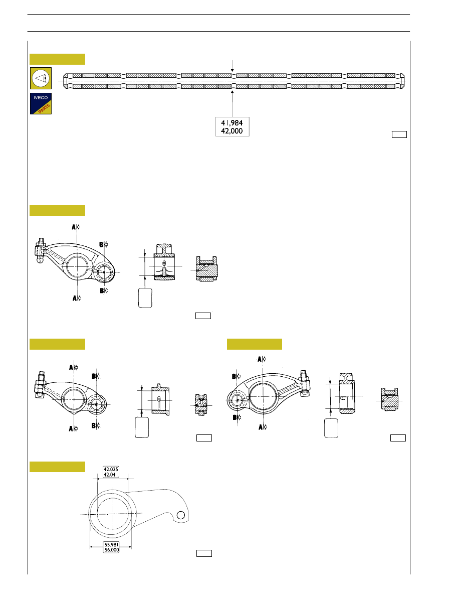
ROCKER SHAFT
Figure 105
87051
86290
- Mount the springs (6) and the top plate (5).
- Fit the tool 99360263 (2) and secure it with the bracket
(4). Screw down the lever (1) to be able to fit on the
cotters (3). Take off the tool (2).
Should valves not have been overhauled or
replaced, remount them according to numbering
performed on dismounting.
NOTE
Lubricate the valve stem and insert the valves in the
respective valve guides; fit the lower caps (1). Use tool
99360329 to fit the oil seal (2) on the valve guides (3) of the
exhaust valves; then, to fit the valves, proceed as follows.
SECTION 4 - OVERHAUL AND TECHNICAL SPECIFICATIONS
47
73539
Figure 106
44914
44912
44913
Figure 107
Figure 108
Figure 109
PUMP INJECTOR ROCKER ARMS
INTAKE VALVE ROCKER ARMS
Check the surfaces of the bushings, which must show no
signs of scoring or excessive wear; if they do, replace the
rocker arm assembly.
EXHAUST VALVE ROCKER ARMS
Rocker arms
SECTION A-A
SECTION B-B
SECTION A-A
SECTION B-B
SECTION A-A
SECTION B-B
42,
015
42,
071
42,
025
42,
041
56,
030
56,
049
Check that the surface of the shaft shows no scoring or
signs of seizure; if it does, replace it.
MAIN DATA OF THE ROCKER ARM SHAFT
Figure 110
EXHAUST VALVE ROCKER ARM HOLDER LEVER
99376
Shaft
48
SECTION 4 - OVERHAUL AND TECHNICAL SPECIFICATIONS
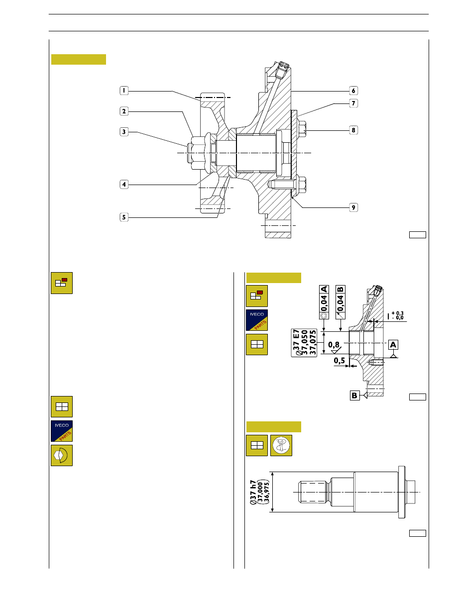
Rated shaft/rear power takeoff supporting bushing backlash
: 0,05
÷ 0,10 mm.
Remove retaining screws (8) and disconnect cover (7) with
seal (9) from support (6).
Lock shaft (3) rotation and remove nut (2) .
Remove from shaft (3): washer (4), gear (1) and spacer (5).
Remove shaft (3) from support (6).
Figure 111
Figure 112
Figure 113
REAR POWER TAKEOFF
107991
1. Gear - 2. Nut - 3. Shaft - 4. Washer - 5. Spacer - 6. Support - 7. Cover - 8. Screw - 9. Seal.
Removal
Refitting
For refitting, reverse operations described for
removal according to instructions below:
- install a new seal (9);
- lubricare shaft shank (3) with engine oil;
- lock screws and nut at prescribed torque.
107992
Shaft
107993
SECTION 4 - OVERHAUL AND TECHNICAL SPECIFICATIONS
49
Нет комментариевНе стесняйтесь поделиться с нами вашим ценным мнением.
Текст