Engine Iveco C10/C13/C78/Cursor 13/Cursor 78. Manual — part 71
86925
86934
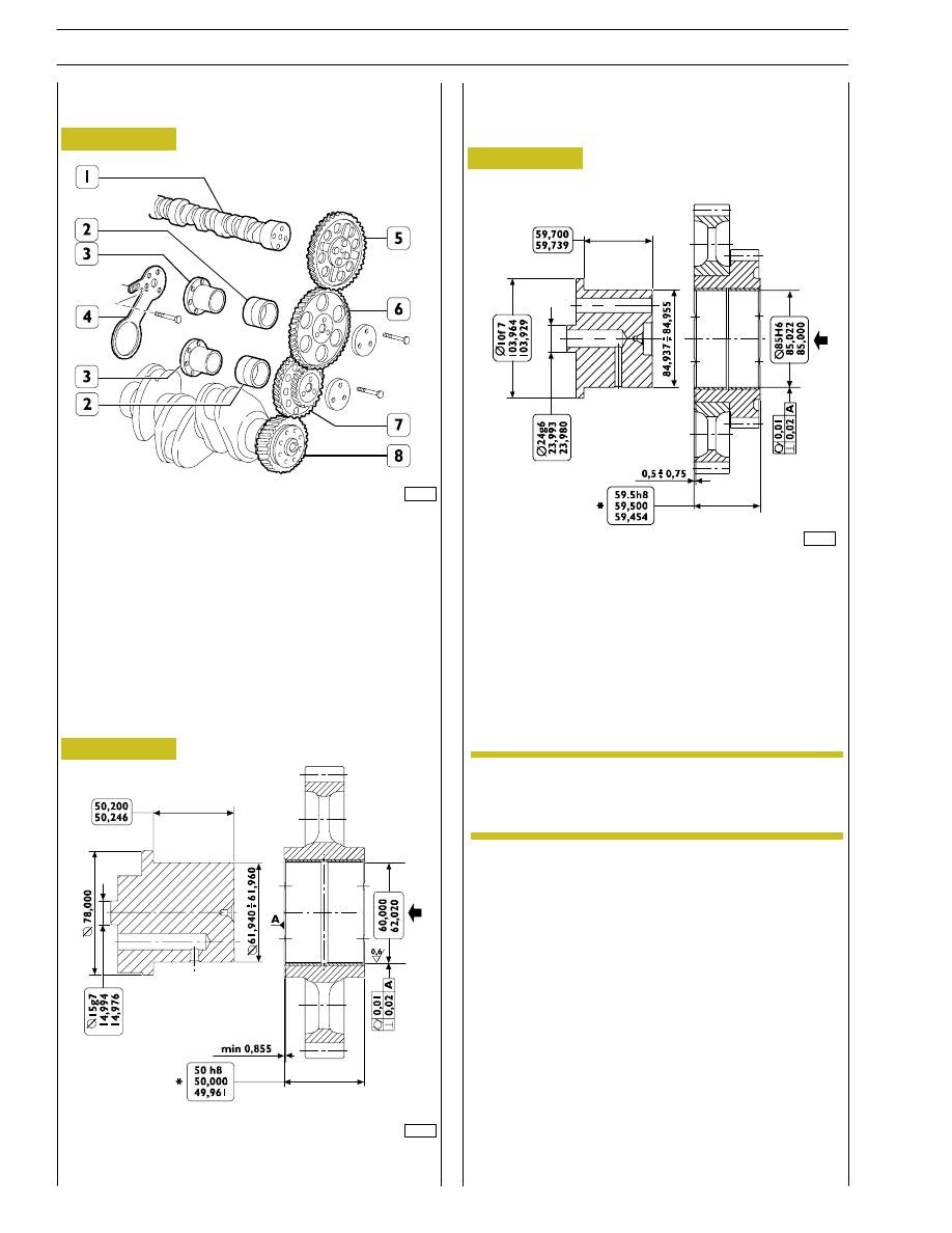
TIMING CONTROL COMPONENT PARTS
1. Camshaft - 2. Bushing - 3. Pin - 4. Articulated rod -
5. Camshaft control gear - 6. Idler gear - 7. Twin idler gear
- 8. Drive shaft driving gear.
TIMING GEAR
Camshaft drive
Idler gear pin
Idler gear
87258
Twin intermediate gear pin
Twin idler gear
Replacing the bushings
Gear bushings shown on Figures 82 - 83 can be replaced
when they are worn. Put up the bushing, then bore it to
obtain the diameter shown on Figure 89 or Figure 90.
The bushing must be driven into the gear by
following the direction of the arrow and setting the
latter to the dimension shown on Figure 89 or
Figure 90.
Rated assembling play between gear bushings and pins:
Figure 89 — 0.040
÷ 0.080 mm
Figure 90 — 0.045
÷ 0.085 mm.
Figure 88
Figure 89
Figure 90
NOTE
42
SECTION 4 - OVERHAUL AND TECHNICAL SPECIFICATIONS
47506
47505
47507
Figure 91
Figure 92
Figure 93
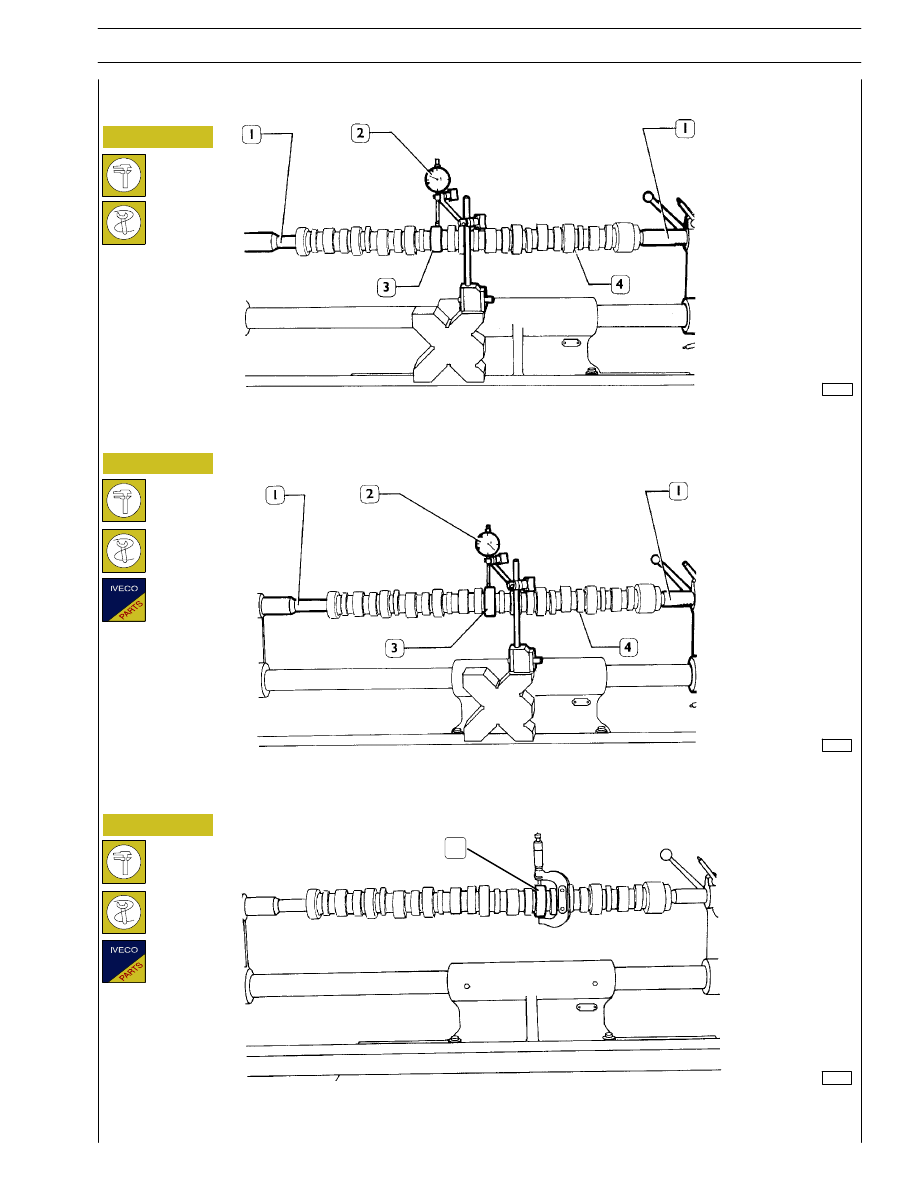
Camshaft
Checking cam lift and pin alignment
When the camshaft (4) is on the tailstock (1), check alignment of supporting pin (3) using a centesimal gauge (2); it must not
exceed 0.035 mm. If misalignment exceeds this value, replace the shaft.
In order to check installation clearance, measure bush inner diameter and camshaft pin (1) diameter; the real clearance is obtained
by their difference.
If clearance exceeds 0.150 mm, replace bushes and, if necessary, the camshaft.
Place the camshaft (4) on the tailstock (1) and check cam lift (3) using a centesimal gauge (2); values are shown in table on page 9.
1
SECTION 4 - OVERHAUL AND TECHNICAL SPECIFICATIONS
43
The bush surfaces must not show any sign of seizing or
scoring; if they do replace them.
60626
60627
Figure 94
Figure 95
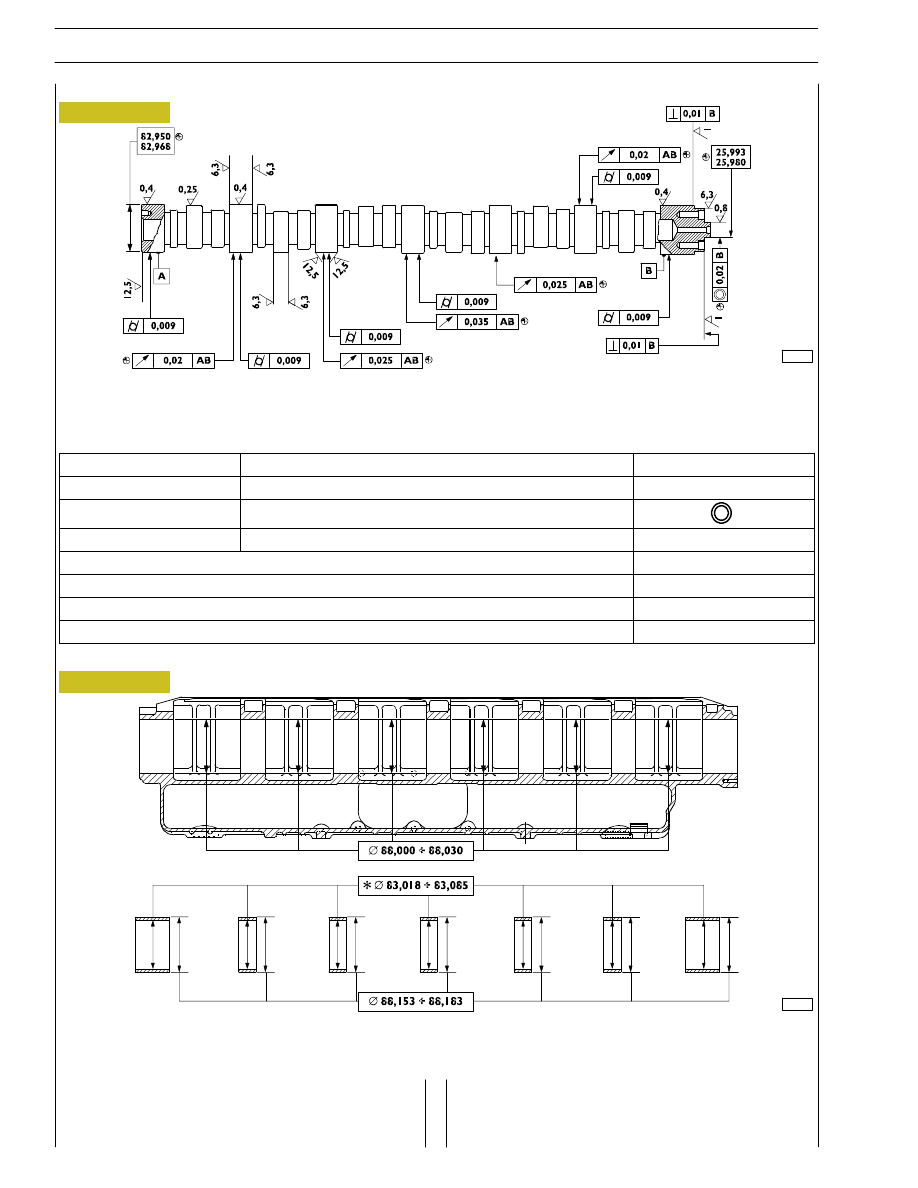
MAIN DATA - CAMSHAFT AND TOLERANCES
The surfaces of shaft supporting pin and cams must be extremely smooth; if you see any sign of seizing
or scoring, replace the shaft and the relative bushes.
MAIN DATA OF CAMSHAFT BUSHES AND RELEVANT HOUSINGS ON CYLINDER HEAD
* Bush inner diameter after installation
Bushings
Measure the bush inner diameters with a baremeter and replace
them, if the value measured exceeds the tolerance value.
To take down and fit back the bushes, use the proper tool
99360499.
Camshaft
44
SECTION 4 - OVERHAUL AND TECHNICAL SPECIFICATIONS
‘
TOLERANCES
TOLERANCE CHARACTERISTIC
SYMBOL
ORIENTATION
Perpendicularity
⊥
POSITION
Concentricity or coaxial alignment
OSCILLATION
Circular oscillation
↗
IMPORTANCE CLASS ASSIGNED TO PRODUCT CHARACTERISTICS
SYMBOL
CRITICAL
©
IMPORTANT
⊕
SECONDARY
⊝
77795
71721
Figure 96
Figure 97
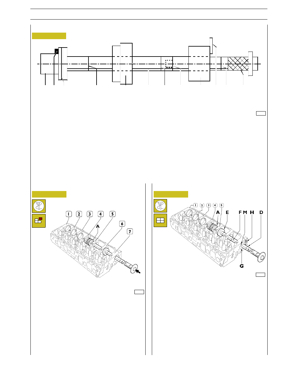
A
=
Drift with seat for bushings to insert/extract.
B
=
Grub screw for positioning bushings.
C
=
Reference mark to insert seventh bushing correctly.
D
=
Reference mark to insert bushings 1, 2, 3, 4, 5, 6 correctly (red marks).
E
=
Guide bushing.
F
=
Guide line.
G
=
Guide bushing to secure to the seventh bushing mount.
H
=
Plate fixing bushing G to cylinder head.
I
=
Grip.
L
=
Extension coupling.
Assemble the drift together with the extension.
To insert bushings 1, 2, 3, 4 and 5, proceed as follows:
4 position the bushing to insert on the drift (A) making the
grub screw on it coincide with the seat (B) (Figure 96) on
the bushing.
5 position the guide bushing (E) and secure the guide
bushing (G) (Figure 96) on the seat of the 7
th
bushing
with the plate (H).
6 while driving in the bushing, make the reference mark (F)
match the mark (M). In this way, when it is driven home,
the lubrication hole on the bushing will coincide with the
oil pipe in its seat.
The bushing is driven home when the 1
st
red reference
mark (D) is flush with the guide bushing (G).
71725
Figure 98
The sequence for removing the bushings is 7, 6, 5, 4, 3, 2, 1.
The bushings are extracted from the front of the single seats.
Removal does not require the drift extension for bushings 5,
6 and 7 and it is not necessary to use the guide bushing.
For bushings 1, 2, 3 and 4 it is necessary to use the extension
and the guide bushings.
Position the drift accurately during the phase of removal.
Removal
Assembly
Front
Rear
A B C
D
E
F
D
L
G
H D
I
Replacing camshaft bushings with drift 99360499
SECTION 4 - OVERHAUL AND TECHNICAL SPECIFICATIONS
45
Нет комментариевНе стесняйтесь поделиться с нами вашим ценным мнением.
Текст