Engine Iveco C10/C13/C78/Cursor 13/Cursor 78. Manual — part 20
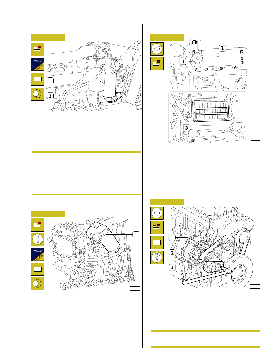
Figure 106
108395
Replace fuel sedimentation tank prefilter (when it is
required by the application)
Disconnect electric connector. Unlock prefilter (1) and
change it. Before refitting a new cartridge, wet seal with fuel
oil or engine oil. Lock cartridge by hand till in contact with
support, then lock it by
¾ of a rev. at predefined tightening
torque.
At change, filter cartridge must not be prefilled to
prevent
circulating
dirt
that
could
damage
injector/pump system components. Bleed air from
fuel filter as described in previous pages.
Figure 107
112859
Fuel filter change
Use tool 99360314 to remove fuel filter (1).
Before fitting the new cartridge, wet seal with fuel oil or engine
oil. Lock the new one by hand and carefully check that rubber
seal and contact surface are clean and in perfect conditions.
Lock cartridge by hand till contact with support and then lock
it for
¾ of a rev. at prescribed tightening torque. Bleed air from
supply system as described in paragraph below:
Check Blow-by filter conditions by means of a clogging
indicator
Figure 108
72563
- Check filter (3) conditions by means of a clogging
indicator (1). In case the red area appears, change it.
- For screw (2) change, remove carter, pull out filter (3) and
replace it with a new one. Filter has a one-way operation,
therefore it must be installed with the two reinforcement
bars visible, as shown in the picture.
Check of water pump/alternator control belt condition
Figure 109
107903
Visually check that belt (1) is not worn out or broken; change
it as described below, if required.
Water pump/alternator control belt change
In order to remove and refit belt (1), operate using a specific
tool (3) on belt tensioner (2) in direction shown by arrow.
Belt tensioner is
automatic and requires no
adjustment.
NOTE
NOTE
SECTION 3 - INDUSTRIAL APPLICATION
61
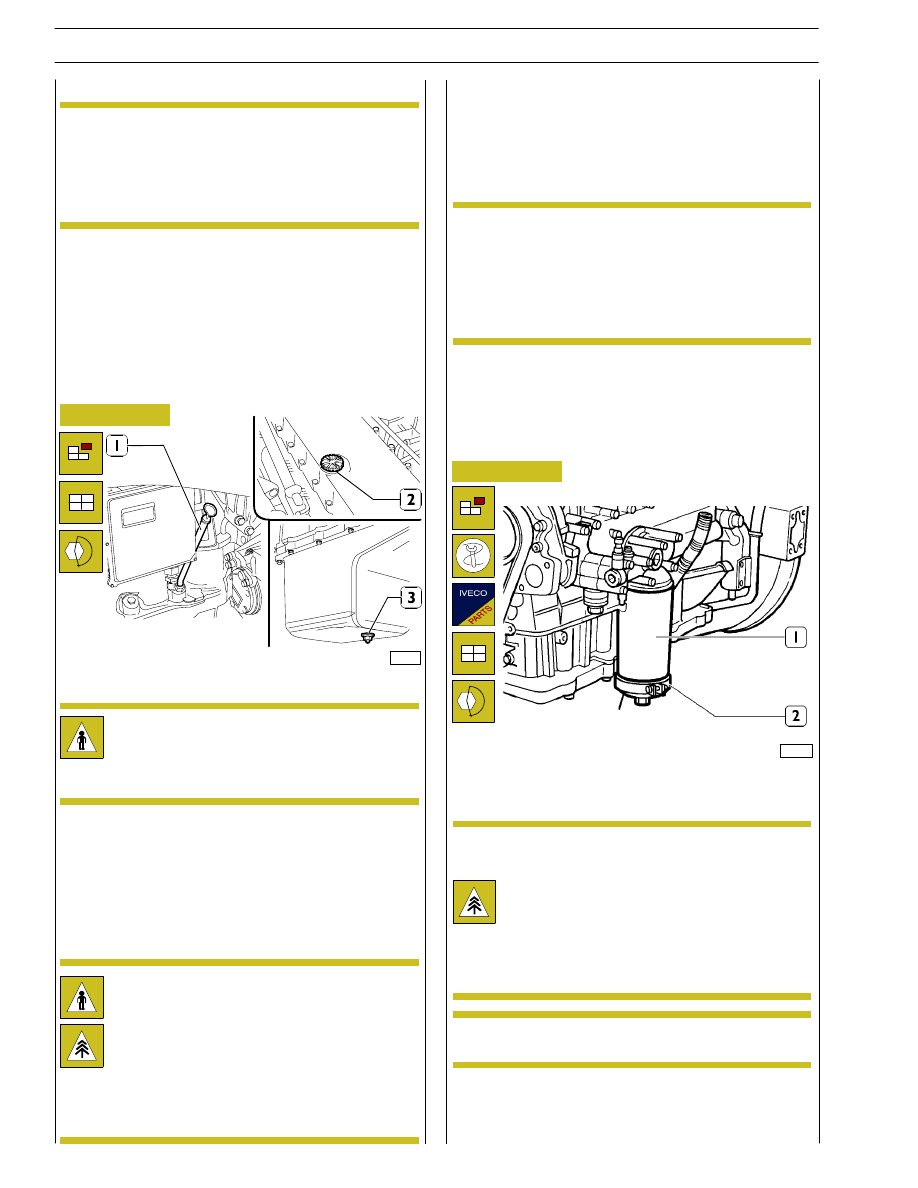
Check for any water in the fuel filter
The components of the system can be damaged
very quickly in presence of water or impurity within
the fuel.
Take prompt action on the filter to drain off the
water in the fuel circuit.
Fuel filter is equipped with pump screw-valve to drain the
water eventually mixed with fuel.
Place a container underneath the filter and slightly loosen the
screw. Drain the water eventually contained in the filter’s
bottom.
Lock the screw (max 0.5 Nm locking couple) as soon as fuel
starts bleeding.
NOTE
Figure 110
85493
We recommend to carry out the oil drainage when the motor
is hot.
Engine oil change
- Place a proper container for the oil collecting under the
pan connected with the drain plug (3).
- Unscrew the plug (3) and then take out the control dip-
sick (1) and the inserting plug (2) to ease the downflow
of the lubrication oil.
Warning: We recommend to wear proper protec-
tions because of high motor service temperature.
The motor oil reaches very high temperature: you
must always wear protection gloves.
The oil motor is very pollutant and harmful.
In case of contact with the skin, wash with much water
and detergent.
Protect properly skin and eyes: operate according to
safety rules.
Dispose of the residual properly following the rules.
Lock plus (3) under oil sump at predefined tightening torque.
Pour oil in prescribed quantity and quality in engine through
filler (2) of tappet cover.
- After the complete drainage, screw the plug and carry out
the clean oil filling.
Use only the recommended oil or oil having the re-
quested features for the corrrect motor function-
ing.
In case of topping up, don’t mix oils having different
features.
If you don’t comply with theses rules, the service
warranty is no more valid.
- Check the level through the dipsick until when the filling
is next to the maximum level notch indicated on the dip-
sick.
NOTE
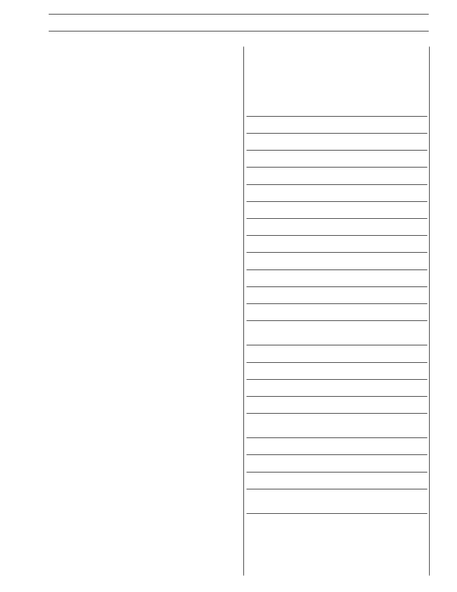
Engine oil filter change
Figure 111
107940
Warning: the oil filter contains inside a quantity of
oil of about 1 kg.
Place properly a container for the liquid.
Warning: avoid the contact of skin with the motor
oil: in case of contact wash the skin with running
water.
The motor oil is very pollutant: it must be disposed
of according to the rules.
Drain oil as described in “Engine oil change” chapter. Use tool
99360314 (2) to remove the oil filter (1).
Before refitting the new cartridge, wet seal using
engine oil.
NOTE
Lock oil filter (1) by hand till contact to support and then lock
by
¾ of a rev. at prescribed tightening torque; pour oil in
engine ad described in “Engine oil change” chapter.
NOTE
62
SECTION 3 - INDUSTRIAL APPLICATION

SECTION 3 - INDUSTRIAL APPLICATION
63
Valve lash check a adjustment
For correct operation, follow instructions contained in related
chapter in section 3 — Industrial Applications.
Change dry air filter and clean its container
Refit container cover, remove cartridge from air filter.
Carefully clean container inside, insert new cartridge and refit
cover.
SECTION 4 - OVERHAUL AND TECHNICAL SPECIFICATIONS
1
SECTION 4
Overhaul and technical specifications
Page
GENERAL CHARACTERISTICS
3
. . . . . . . . . . . . .
ASSEMBLY CLEARANCE DATA
5
. . . . . . . . . . . .
ENGINE OVERHAUL
11
. . . . . . . . . . . . . . . . . . . . .
ENGINE REMOVAL AT THE BENCH
11
. . . . . . . .
REPAIR OPERATIONS
12
. . . . . . . . . . . . . . . . . . . .
CYLINDER BLOCK
12
. . . . . . . . . . . . . . . . . . . . . . .
- Checks and measurements
12
. . . . . . . . . . . . . . .
CYLINDER LINERS
13
. . . . . . . . . . . . . . . . . . . . . . .
- Replacing cylinder liners
14
. . . . . . . . . . . . . . . . .
- Removal
14
. . . . . . . . . . . . . . . . . . . . . . . . . . . . .
- Fitting and checking protrusion
14
. . . . . . . . . . . .
CRANKSHAFT
15
. . . . . . . . . . . . . . . . . . . . . . . . . .
- Measuring main journals and crank pins
16
. . . . .
PRELIMINARY MEASUREMENT OF MAIN AND
BIG END BEARING SHELL SELECTION DATA
17
- Replacing the timing control gear and the oil pump 24
- Checking main journal installation clearance
24
. .
- Checking crankshaft end float
25
. . . . . . . . . . . . .
ASSEMBLING THE ENGINE ON THE BENCH
26
.
DIAGRAM SHOWING THE UNDERBLOCK FIXING
SCREWS TIGHTENING ORDER
27
. . . . . . . . .
PISTON-CONNECTING ROD ASSEMBLY
28
. . . .
- Removal
28
. . . . . . . . . . . . . . . . . . . . . . . . . . . . .
- Measuring the diameter of the pistons
29
. . . . . .
- Conditions for correct gudgeon pin-piston
coupling
29
. . . . . . . . . . . . . . . . . . . . . . . . . . . . . .
Нет комментариевНе стесняйтесь поделиться с нами вашим ценным мнением.
Текст