Engine Iveco C10/C13/C78/Cursor 13/Cursor 78. Manual — part 21

2
SECTION 4 - OVERHAUL AND TECHNICAL SPECIFICATIONS
Page
- Piston rings
30
. . . . . . . . . . . . . . . . . . . . . . . . . . . .
CONNECTING ROD
31
. . . . . . . . . . . . . . . . . . . . .
- Bushings
32
. . . . . . . . . . . . . . . . . . . . . . . . . . . . . .
- Checking connecting rods
32
. . . . . . . . . . . . . . . .
- Mounting the connecting rod — piston assembly
33
- Mounting the piston rings
33
. . . . . . . . . . . . . . . .
- Fitting the big end bearing shells
33
. . . . . . . . . . .
- Fitting the connecting rod-piston assembly
into the piston liners
34
. . . . . . . . . . . . . . . . . . . .
- Piston protrusion check
34
. . . . . . . . . . . . . . . . . .
- Checking assembly clearance of big end pins
35
. .
CYLINDER HEAD
35
. . . . . . . . . . . . . . . . . . . . . . . .
- Dismounting the valves
35
. . . . . . . . . . . . . . . . . .
- Checking the planarity of the head on the
cylinder block
35
. . . . . . . . . . . . . . . . . . . . . . . . . .
VALVE
36
. . . . . . . . . . . . . . . . . . . . . . . . . . . . . . . . .
- Removing deposits and checking the valves
36
. . .
- Valve seats
36
. . . . . . . . . . . . . . . . . . . . . . . . . . . .
- Checking clearance between valve-stem and
associated valve guide
37
. . . . . . . . . . . . . . . . . . .
- Valve guides
37
. . . . . . . . . . . . . . . . . . . . . . . . . . .
REPLACING INJECTOR HOLDER CASES
37
. . . . .
- Removal
37
. . . . . . . . . . . . . . . . . . . . . . . . . . . . . .
Page
- Checking protrusion of injectors
39
. . . . . . . . . . .
TIMING GEAR
40
. . . . . . . . . . . . . . . . . . . . . . . . . .
- Camshaft drive
40
. . . . . . . . . . . . . . . . . . . . . . . . .
- Intermediate gear pin
40
. . . . . . . . . . . . . . . . . . . .
- Idler gear
40
. . . . . . . . . . . . . . . . . . . . . . . . . . . . .
- Twin idler gear
40
. . . . . . . . . . . . . . . . . . . . . . . . .
- Replacing the bushings
40
. . . . . . . . . . . . . . . . . . .
- Camshaft
41
. . . . . . . . . . . . . . . . . . . . . . . . . . . . .
- Checking cam lift and pin alignment
41
. . . . . . . . .
- Bushes
42
. . . . . . . . . . . . . . . . . . . . . . . . . . . . . . .
- Replacing camshaft bushes using beater 99360487 43
- Removal
43
. . . . . . . . . . . . . . . . . . . . . . . . . . . . . .
- Assembly
43
. . . . . . . . . . . . . . . . . . . . . . . . . . . . .
VALVE SPRINGS
44
. . . . . . . . . . . . . . . . . . . . . . . . .
- Fitting the valves and oil seal ring
44
. . . . . . . . . . .
ROCKER SHAFT
45
. . . . . . . . . . . . . . . . . . . . . . . . .
- Shaft
45
. . . . . . . . . . . . . . . . . . . . . . . . . . . . . . . . .
- Rocker
45
. . . . . . . . . . . . . . . . . . . . . . . . . . . . . . .
TIGHTENING TORQUES
46
. . . . . . . . . . . . . . . . .
SECTION 4 - OVERHAUL AND TECHNICAL SPECIFICATIONS
3
GENERAL CHARACTERISTICS
Type
F2B
Cycle
Diesel 4 strokes
Feeding
Turbocharged
Injection
Direct
N. of cylinders
6 on-line
∅
Diameter
mm
115
Stroke
mm
125
+
+
+.. =
Total displacement
cm
3
7790

4
SECTION 4 - OVERHAUL AND TECHNICAL SPECIFICATIONS
Type
F2B
A
B
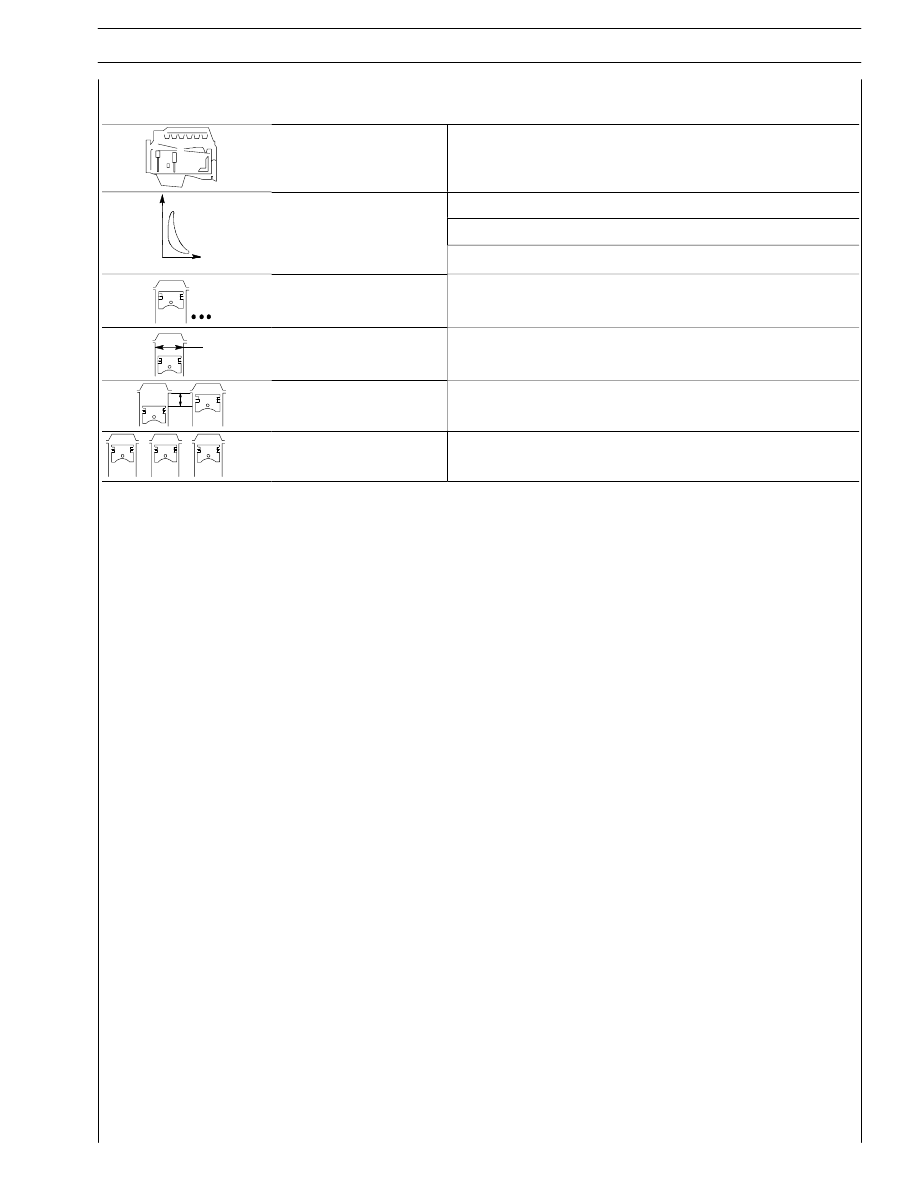
VALVE TIMING
opens before T.D.C.
A
closes after B.D.C.
B
17
°
31
°
C
D
opens before B.D.C.
D
closes after T.D.C.
C
48
°
9
°
X
For timing check
mm
X
mm
Running
mm
X
mm
_
_
0.40 to 0.50
0.40 to 0.50
FEED
Through fuel pump - filters
Injection
type: Bosch
With electronically regulated injectors PDE 30
pump injectors controlled by overhead camshaft
MS6.2 ECU
Nozzle type
DLLA 143P894
Nozzle type
DLLA 143P894
Injection order
1 - 4 - 2 - 6 - 3 - 5
bar
Injection pressure
bar
Injector calibration
bar
1500
-
SECTION 4 - OVERHAUL AND TECHNICAL SPECIFICATIONS
5
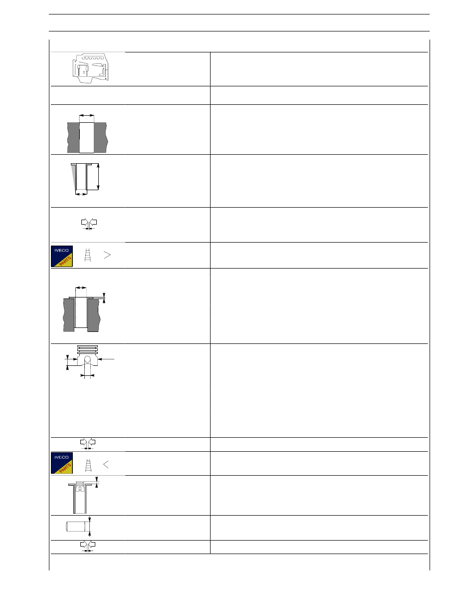
ASSEMBLY CLEARANCE DATA
Type
F2B
CYLINDER BLOCK AND CRANK
MECHANISM COMPONENTS
mm
∅
1
Cylinder sleeve bore
upper
∅ 1
lower
130.200 to 130.225
128.510 to 128.535
Cylinder liners:
L
∅
outer diameter:
upper
∅ 2
lower
130.161 to 130.186
128.475 to 128.500
∅2
length
L
Cylinder sleeve -
crankcase bore
upper
lower
0.014 to 0.064
0.010 to 0.060
Outside diameter
∅ 2
Cylinder sleeve
∅
3
inside diameter
∅3
A*
115.000 to 115.012
X
inside diameter
∅3
B*
115.010 to 115.022
Protrusion
X
0.035 to 0.065
* Available dia. class
∅
1
Pistons:
∅
1
X
measuring dimension
X
18
X
outside diameter
∅ 1 A•
114.888 to 114.900
∅
2
outside diameter
∅ 1 B••
114.898 to 114.910
outside diameter
∅ 2
46.010 to 46.018
114.898 to 114.910
• Class A pistons supplied as spares.
•• Class B pistons are fitted in production only and
are not supplied as spares.
Piston - cylinder sleeve
0.100 to 0.124
Piston diameter
∅ 1
_
X
Pistons protrusion
X
-
3
∅
Gudgeon pin
∅ 3
45.994 to 46.000
Gudgeon pin - pin housing
0.010 to 0.024
Нет комментариевНе стесняйтесь поделиться с нами вашим ценным мнением.
Текст