Engine Iveco C10/C13/C78/Cursor 13/Cursor 78. Manual — part 9
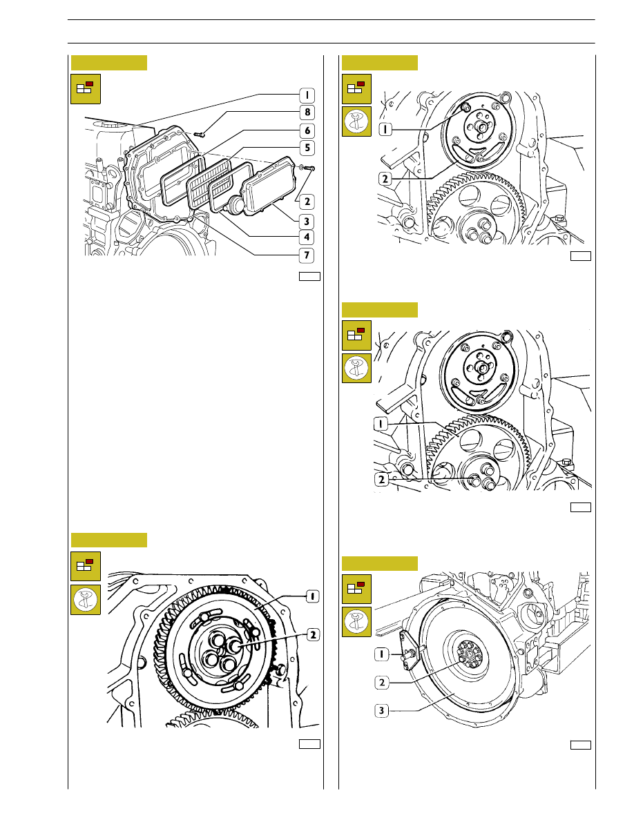
Figure 17
Figure 18
Figure 19
Figure 20
Figure 21
84377
Remove the rocker arm cover (1), take off the screws (2) and
remove: the cover (3), the filter (5) and the gaskets (4 and 6).
Take off the screws (8) and remove the blow-by case (7).
45661
Unscrew the screws (2), by using the proper wrench and
remove the gear (1) with the phonic wheel.
86289
47568
By means of a properly splined wrench, untighten screws (2)
and remove the transmission gear (1).
Unscrew the screws (1); tighten a screw in a reaction hole and
remove the shoulder plate (2), remove the sheet gasket.
47568
Stop the engine flywheel (3) rotation by means of tool
99360351 (1), untighten the fixing screws (2) and remove the
engine flywheel.
SECTION 3 - INDUSTRIAL APPLICATION
11
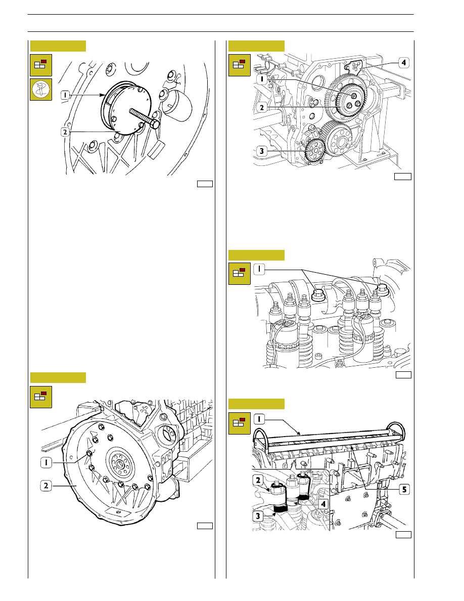
Figure 22
Figure 23
Figure 24
45257
Apply extractor 99340052 (2) and pull out the seal gasket (1).
Untighten the screws (1) and take down the gear box (2).
Figure 25
Figure 26
In sequence, take out the:
- if the P.T.O. control gear (1) is present (if available);
- idle gear (2);
- link rod (4);
- oil pump (3);
47569
- Untighten the fixing screws (1) of rocker arm shaft.
99261
- Using tool 99360144 (3), constrain the blocks (4) to the
rockers (2).
- Apply tool 99360553 (1) to the rocker holder shaft (5)
and remove the shaft (5) from the cylinder head.
107965
73533
12
SECTION 3 - INDUSTRIAL APPLICATION
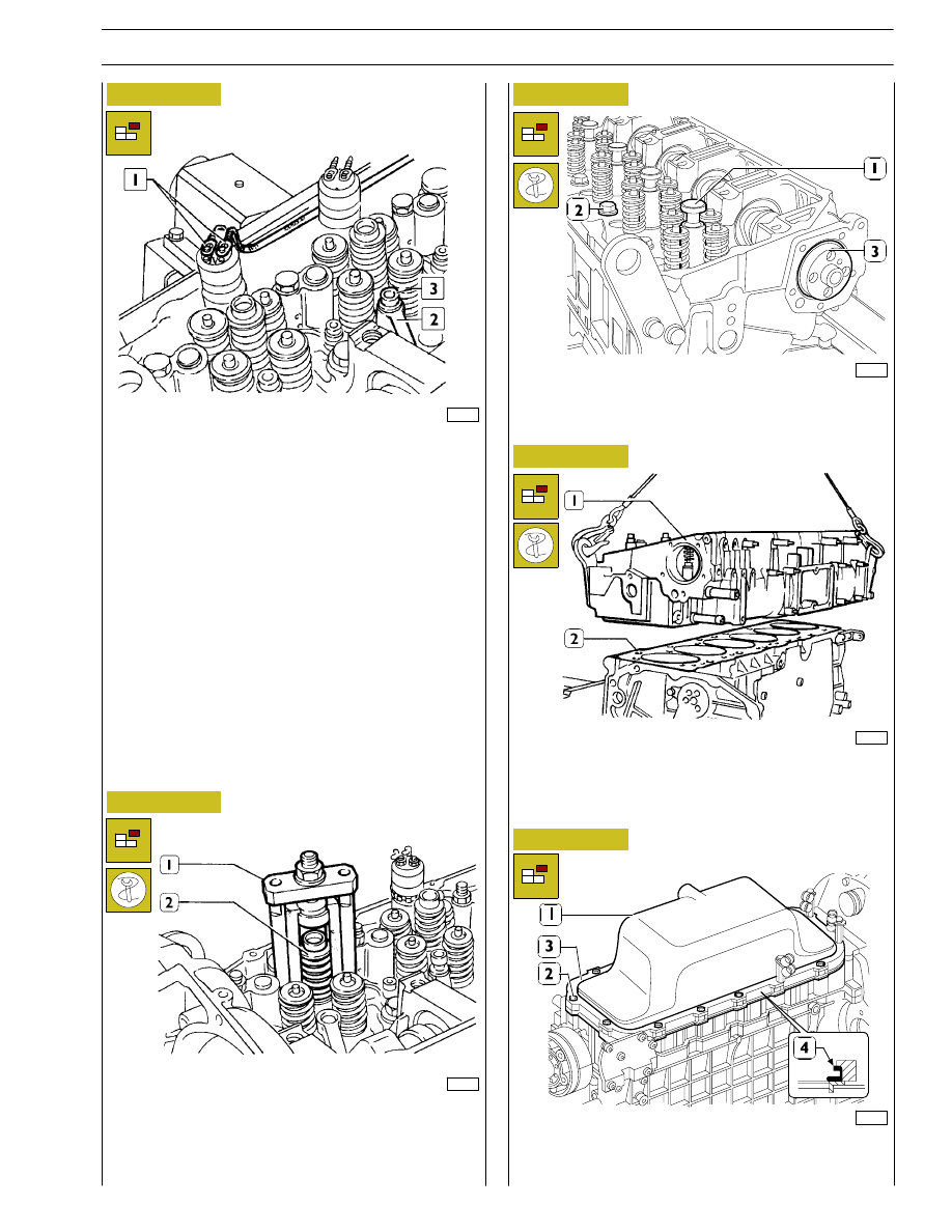
Figure 27
Figure 28
Figure 29
Figure 30
Figure 31
99266
- Untighten screws and remove electric connections (1)
from solenoid valves;
- Untighten fixing screws (2) of injector brackets (3).
- Remove injectors (2)
If this operations is difficult, use extractor 99342148 (1).
45263
99267
Fit the plugs 99360177 (1) in place of the injectors.
Take out the camshaft (3).
Take out the screws (2) fixing the cylinder head.
45266
- By means of wire ropes, lift the cylinder head (1) and
remove seals (2).
99268
Untighten screws (2) and remove the engine oil sump (1) with
spacer (3) and seal (4).
SECTION 3 - INDUSTRIAL APPLICATION
13

Figure 32
Figure 33
Figure 34
Figure 35
Figure 36
Figure 37
By means of centering ring 99396033 (2), check the exact
cover position (1), otherwise act as necessary and tighten the
screws.
Fit the sealing gasket (1), install the fitting tool 99346245 (2)
and drive the sealing gasket (1) by screwing nut (3).
Make sure that pistons 1-6 are exactly at the TDC Place the
sealing gasket (2) on the block. Fit the cylinder head (1) and
tighten screws as shown in figs. 36, 37 and 38.
Diagram showing the cylinder head fixing screws tightening
order
- Preliminary tightening by means of a dynamometric
wrench (1):
1
st
phase: 50 Nm (5 kgm:
2
nd
phase: 100 Nm (10 kgm)
45267
44900
99269
Undo the screws and remove the suction strainer (1).
ASSEMBLING
THE
ENGINE
ON
THE
BENCH
45266
45255
45256
14
SECTION 3 - INDUSTRIAL APPLICATION
Нет комментариевНе стесняйтесь поделиться с нами вашим ценным мнением.
Текст