Engine Iveco C10/C13/C78/Cursor 13/Cursor 78. Manual — part 10
Engines without power take--off
Tighten the screws shown in the figure by means of a
dynamometric wrench, in compliance with the following order and
tightening torque:
no. 1 screw M10 x 1.5 x 100 tightening torque 42 Nm
no. 13 screws M12 x 1.75 x 80 tightening torque 63 Nm
no. 1 screw M10 x 1.5 x 180 tightening torque 42 Nm
no. 3 screws M10 x 1.5 x 35 tightening torque 42 Nm
Figure 38
Figure 39
Figure 40
45268
- Angle closing by means of tool 99395216 (1):
3
rd
phase: 90
° angle
4
th
phase: 75
° angle
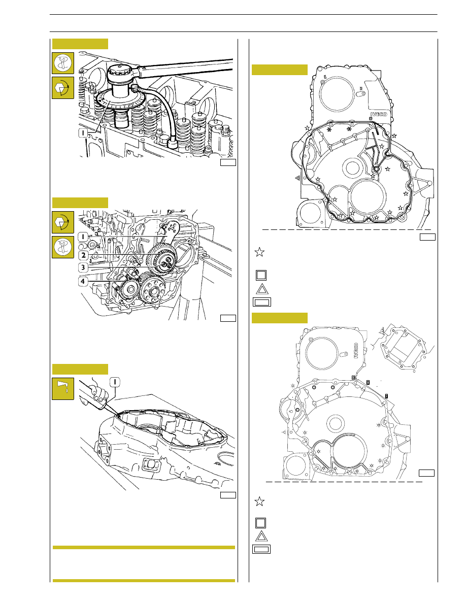
Fit the oil pump (4), intermediate gears (2) with rod (1) and
tighten screws (3) in two phases:
preliminary tightening
30 Nm
angle closing
90
°
Apply sealant LOCTITE 5970 IVECO No. 2992644 to the
gear box using the proper equipment (1).
The sealer string (1) diameter is to be 1,5
±
47592
47597
47598
Figure 41
α
Install the gear box within 10’ of the application of
the sealant.
α
no. 2 screws M18 x 1.25 x 125 tightening torque
24 Nm
:
Engines with power take--off (if available)
no. 1 screw M10 x 1.5 x 170 tightening torque 42 Nm
no. 10 screws M12 x 1.75 x 80 tightening torque 63 Nm
no. 1 screw M10 x 1.5 x 180 tightening torque 42 Nm
no. 3 screws M10 x 1.5 x 35 tightening torque 42 Nm
84390
no. 2 screws M12 x 1.75 x 125 tightening torque 63
Nm
¬
d
no. 8 screw M10 x 1,5 x 120
◊
no. 2 screw M10 x 1,5 x 120 (apply to the thread
LOCTITE 275)
Figure 42
0.5
0.2
NOTE
SECTION 3 - INDUSTRIAL APPLICATION
15
16
SECTION 3 - INDUSTRIAL APPLICATION
Second phase: closing to angle of 60
° with tool 99395216 (1).
49036
α
Figure 43
Figure 44
The crankshaft has a locating peg that has to couple
with the relevant seat on the engine flywheel.
49037
Figure 45
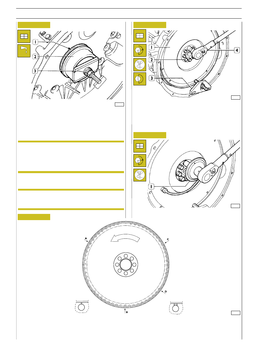
Position the flywheel (1) on the crankshaft, lubricate the
thread of the screws (2) with engine oil and screw them down.
Lock rotation with tool 99360351 (3). Lock the screws (2) in
three phases.
First phase: pre-tightening with torque wrench (4) to a torque
of 100 Nm (10 kgm).
If the teeth of the ring gear mounted on the engine
flywheel, for starting the engine, are very damaged,
replace the ring gear. It must be fitted after heating
the ring gear to a temperature of approx. 200
°C.
α
Fitting engine flywheel
Fit the sealing gasket (1), install the fitting tool 99346246 (2)
and drive the sealing gasket by screwing the nut (3).
45258
ENGINE FLYWHEEL
60668
DETAIL OF PUNCH MARKS ON ENGINE FLYWHEEL FOR PISTON POSITIONS
A. Hole on flywheel with one reference mark, corresponding to the TDC of pistons 3-4. - B. Hole on flywheel with one reference
mark, corresponding to the TDC of pistons 1-6. - C. Hole on flywheel with one reference mark, corresponding
to the TDC of pistons 2-5. - D. Hole on flywheel with two reference marks, position corresponding to 54
°.
VIEW OF HOLES:
A - B - C
VIEW OF HOLES:
D
Figure 46
NOTE
NOTE
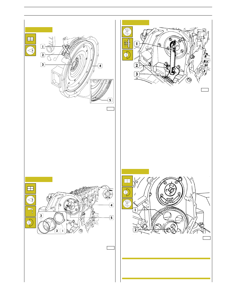
Figure 47
Figure 48
Fit the camshaft (4), positioning it observing the reference
marks (
→) as shown in the figure.
Lubricate the seal (3) and fit it on the shoulder plate (2).
Mount the shoulder plate (2) with the sheet metal gasket (1)
and tighten the screws (5) to the required torque.
73843
72436
Figure 49
Figure 50
Position the crankshaft with the pistons 1 and 6 at the top dead
centre (T.D.C.).
This situation occurs when:
1. The hole with reference mark (5) of the engine flywheel (4)
can be seen through the inspection window.
2. The tool 99360612 (1), through the seat (2) of the engine
speed sensor, enters the hole (3) in the engine flywheel (4).
If this condition does not occur, turn the engine flywheel (4)
appropriately.
Remove the tool 99360612 (1).
Replace the idle gear bushing (1) when wear is
detected. After installing the bushing, adjust it to j
58.010
± 0.10 mm.
- Apply gauge 99395215 (1), check and record the position
of the rod (3) for the transmission gear, tighten the screw
(2) to the prescribed torque.
45376
- Remove the transmission gear (1) and tighten screws (2)
by means of proper splined wrench, to the prescribed
torque.
45269
Fitting camshaft
NOTE
SECTION 3 - INDUSTRIAL APPLICATION
17
18
SECTION 3 - INDUSTRIAL APPLICATION
5
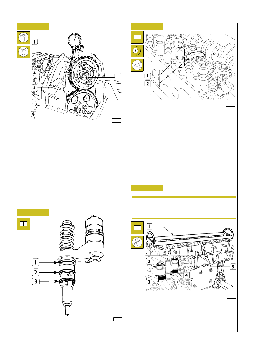
Position the gear (2) on the camshaft so that the 4 slots are
centred with the holes for fixing the camshaft, without fully
locking the screws (5).
Using the dial gauge with a magnetic base (1), check that the
clearance between the gears (2 and 3) is 0.073 — 0.195 mm;
if this is not so, adjust the clearance as follows:
- Loosen the screws (4) fixing the idle gear (3).
- Loosen the screw (2, Figure 49) fixing the link rod. Shift
the link rod (3, Figure 49) to obtain the required
clearance.
- Lock the screw (2, Figure 49) fixing the link rod and
screws (4, Figure 49) fixing the idle gear to the required
torque.
44908
Fit the seals (1) (2) (3) on the injectors.
Before refitting the rocker-arm shaft assembly,
make sure that all the adjustment screws have been
fully unscrewed.
Using tool 99360144 (3), fasten the blocks (4) to the rocker
arms (2).
Apply the tool 99360553 (1) to the rocker arm shaft (5) and
mount the shaft on the cylinder head.
73533
Fitting pump-injectors
99284
Mount:
- The injectors (1) and, using a torque wrench, lock the
bracket fixing screws to a torque of 26 Nm.
- The crosspieces (2) on the valve stem, all with the largest
hole on the same side.
Fitting rocker-arm shaft assembly
Figure 51
Figure 52
Figure 53
Figure 54
45270
NOTE
Нет комментариевНе стесняйтесь поделиться с нами вашим ценным мнением.
Текст