Engine Iveco C10/C13/C78/Cursor 13/Cursor 78. Manual — part 64
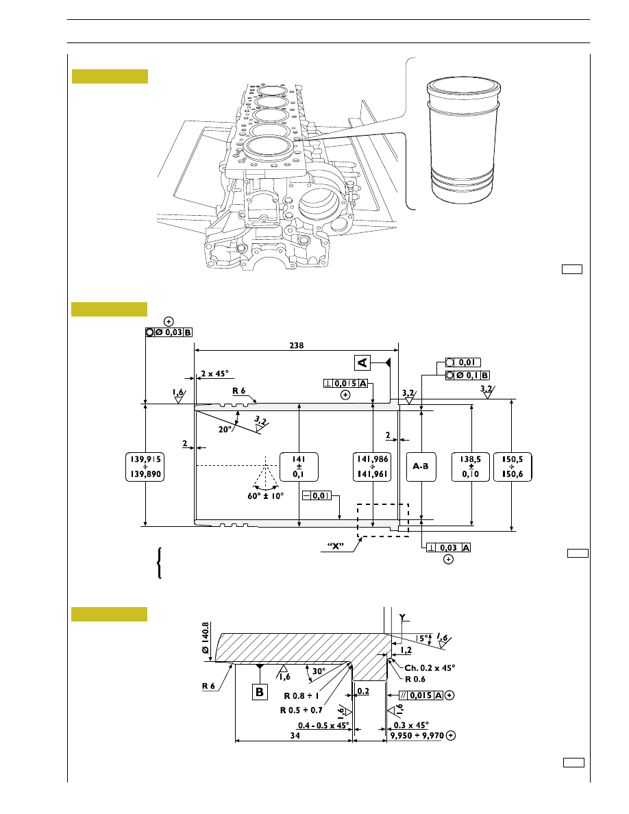
A = Selection class
∅ 125 — 125.013 mm
B = Selection class
∅ 125.011 — 125.024 mm
X = Selection class marking area
In case of maximum wear >0.150 mm or maximum
ovalization >0.100 mm compared to the values indicated in
the figure, the liners must be replaced as they cannot be
ground, lapped or trued.
REPAIR OPERATIONS
CYLINDER BLOCK
Checks and measurements
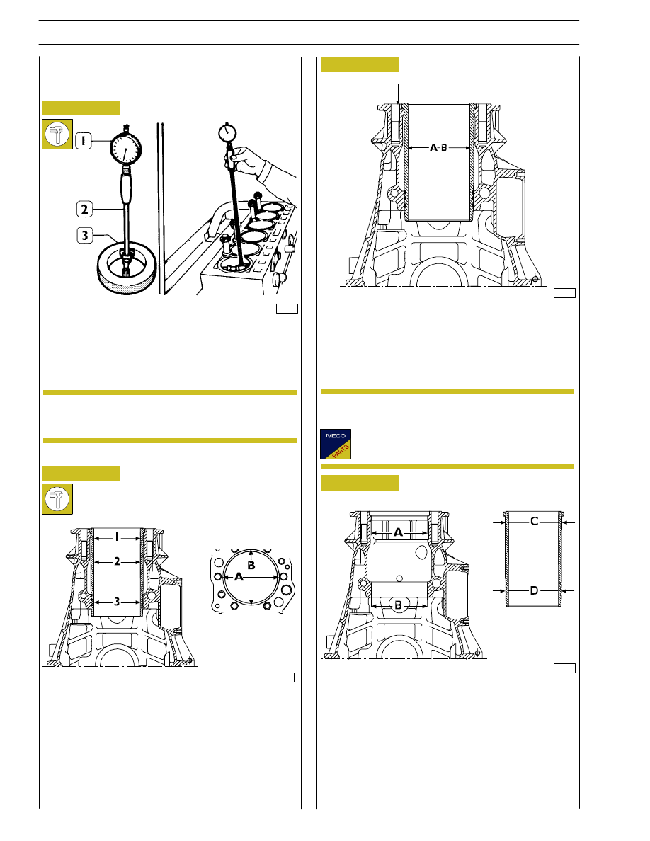
Internal diameter of the cylinder liners is checked for
ovalization, taper and wear, using a bore dial (1) centesimal
gauge 99395687 (2) previously reset to ring gauge (3),
diameter 125 mm.
If a 125 mm ring gauge is not available use a
micrometer caliper.
A = Ø 142.000 to 142.025 mm
B = Ø 140.000 to 140.025 mm
C = Ø 141.961 to 141.986 mm
D = Ø 139.890 to 139.915 mm
The figure shows the outer diameters of the cylinder liners
and the relative seat inner diameters.
The cylinder liners can be extracted and installed several
times in different seats, if necessary.
Check the state of the cylinder assembly machining plugs: if
they are rusty or there is any doubt at all about their seal,
change them.
34994
60595
60597
Figure 6
Figure 7
Figure 8
Figure 9
1 = 1
st
measuring
2 = 2
nd
measuring
3 = 3
rd
measuring
Carry out measurings on each cylinder liner at three different
levels and on two (A-B) surfaces, to one another
perpendicular, as shown in Figure 7.
(Demonstration)
Cylinder liners are equipped with spare parts with
“A“ selection class.
60596
x
NOTE
NOTE
14
SECTION 4 - OVERHAUL AND TECHNICAL SPECIFICATIONS
60600
Figure 10
Figure 11
CYLINDER LINERS MAIN DATA
DETAIL “X”
“Y“ - Selection class marking area
Figure 12
BLOCK WITH CYLINDER LINERS
A 125.000 to 125.013 mm
B 125.011 to 125.024 mm
Selection class
60598
60601
CYLINDER LINERS
SECTION 4 - OVERHAUL AND TECHNICAL SPECIFICATIONS
15
47577
16798
60521
Figure 13
Figure 14
Figure 15
Figure 16
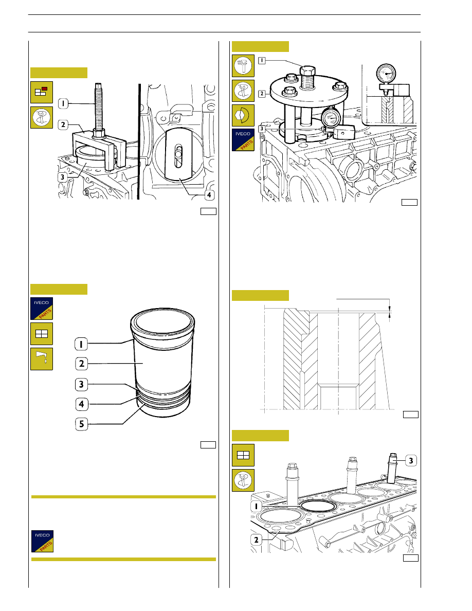
Place details 99360706 (2) and plate 99360726 (4) as shown
in the figure, by making sure that the plate (4) is properly
placed on the cylinder liners.
Tighten the screw nut (1) and remove the cylinder liner (3)
from the block.
Always replace water sealing rings (3, 4 and 5).
Install the adjustment ring (1) on the cylinder liner (2);
lubricate lower part of liner and install it in the cylinder unit
using the proper tool.
Check the protrusion of the cylinder liners, using tool
99360472 (2) and tightening screw (1) to 225 Nm torque.
Using a dial gauge (3), measure the cylinder liner protrusion,
from the cylinder head supporting surface, it must be 0.045
to 0.075 (Figure 16); otherwise, replace the adjustment ring
(1, Figure 14) supplied as spare parts having different
thicknesses.
When the installation is completed, block the cylinder liners
(1) to the block (2) with studs 99360703 (3).
Fitting and checking protrusion
Figure 17
CYLINDER LINER PROTRUSION
49017
The adjustment ring (1) is supplied as spare parts in the
following thicknesses: 0.08 mm - 0.10 mm - 0.12 mm.
60520
0.045 to 0.075
Replacing cylinder liners
Refitting
NOTE
16
SECTION 4 - OVERHAUL AND TECHNICAL SPECIFICATIONS
60604
99369
Figure 18
Figure 19
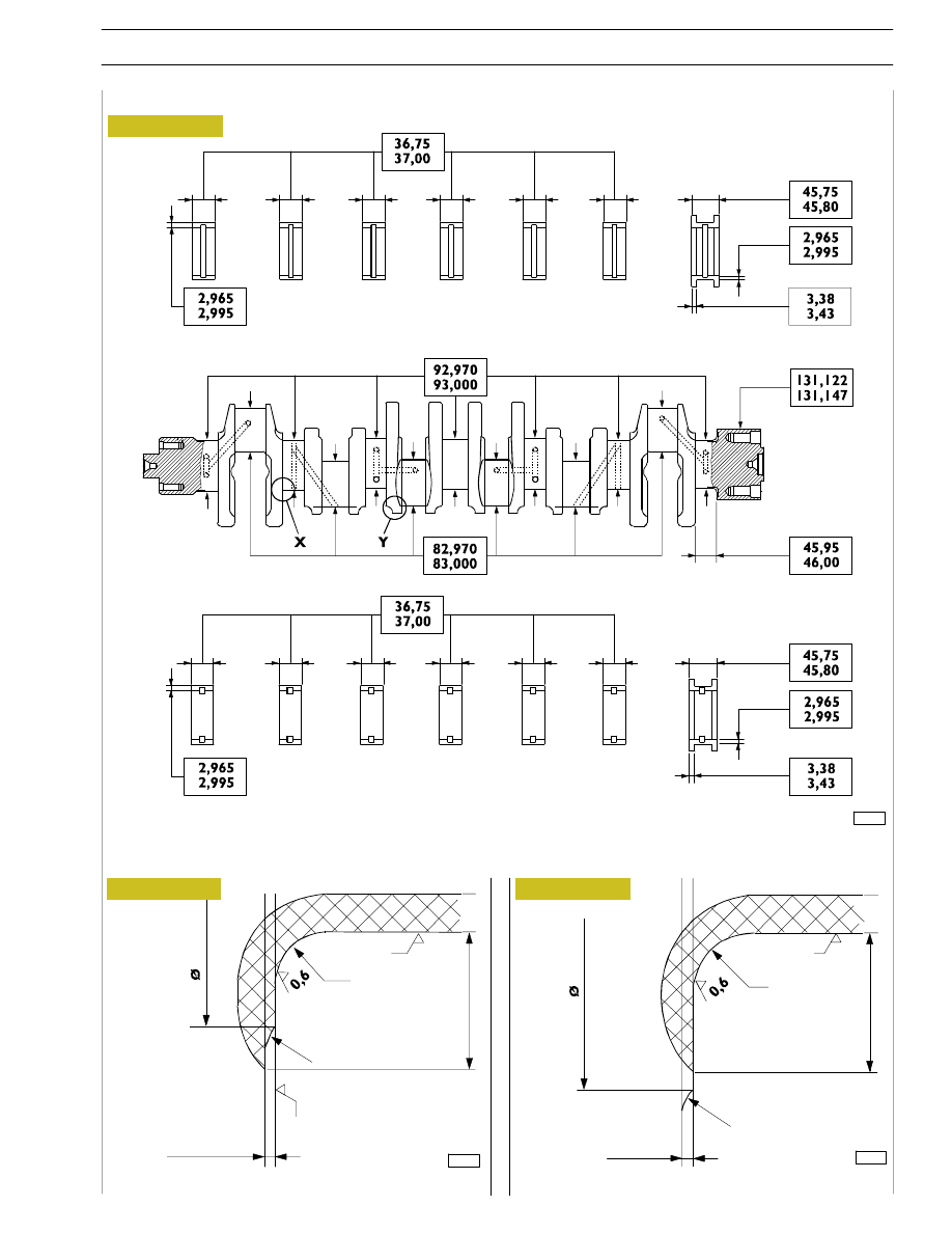
X
. Detail of main journals connections
Y.
Detail of crank pins connections
MAIN DATA FOR THE CRANK SHAFT PINS AND THE HALF BEARINGS
Check the condition of the journals and the big end pins; there must no be signs of scoring,
ovalization or excessive wear. The data given refer to the normal diameter of the pins.
60603
Upper main journal half bearings
Lower main journal half bearings
Figure 20
BUFF
GROUND
GROUND
GROUND
BUFF
108
1.6
R 5
R 3.7 to 4
9t
o
1
2
0.8
±0.3
0.8
±0.3
108
R 5
R 4.2 to 4.5
9t
o
1
2
0.3
0.3
CRANKSHAFT
SECTION 4 - OVERHAUL AND TECHNICAL SPECIFICATIONS
17
Нет комментариевНе стесняйтесь поделиться с нами вашим ценным мнением.
Текст