Engine Iveco C10/C13/C78/Cursor 13/Cursor 78. Manual — part 48
99367
Figure 33
Figure 34
Figure 35
Figure 36
Figure 37
Figure 38
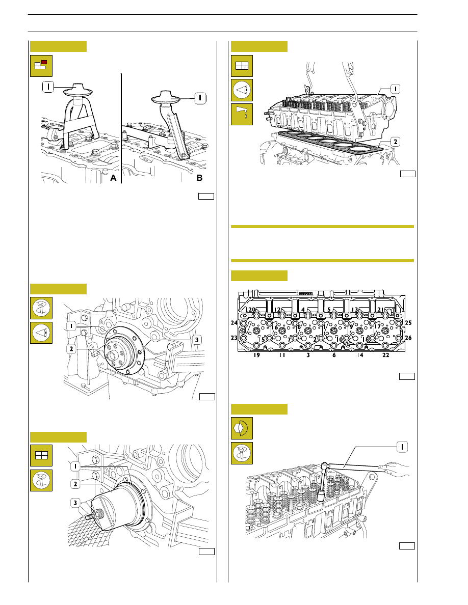
Undo the screws and remove the suction strainer (1).
A. for types: F3AE0684E*B002 - F3AE0684J*B902.
B. for types: F3AE0684D*B001 - F3AE0684G*B003
F3AE0684D*B003.
Using the centring ring 99396035 (2), check the exact position
of the cover (1). If it is wrong, proceed accordingly and lock
the screws (3).
Key on the gasket (1), mount the key 99346250 (2) and,
screwing down the nut (3), drive in the gasket (1).
Check that the pistons 1-6 are exactly at the T.D.C.
Put the gasket (2) on the crankcase.
Mount the cylinder head (1) and tighten the screws as shown
in Figs. 38 - 39 - 40.
Diagram of the tightening sequence of the screws fixing the
cylinder head.
- Pre-tightening with the torque wrench (1):
1
st
phase: 60 Nm (6 kgm).
2
nd
phase: 120 Nm (12 kgm).
60563
60564
60515
60565
61270
Lubricate the thread of the screws with engine oil
before assembly.
ENGINE ASSEMBLY
NOTE
14
SECTION 3 - INDUSTRIAL APPLICATION
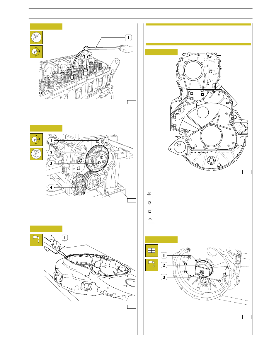
Apply LOCTITE 5970 IVECO n˚ 2992644 silicone on the gear
housing, using appropriate tools (1), as shown in the figure.
The sealer string (1) diameter is to be 1,5
±
Using a torque wrench, tighten the highlighted screws with the
following sequence and tightening torques:
4 screws M12 x 1.75 x 35
63 Nm
10 screws M12 x 1.75 x 100
63 Nm
1 screw M12 x 1.75 x 120
63 Nm
2 screws M12 x 1.75 x 70
63 Nm
Figure 39
Figure 40
Figure 41
60566
- Closing to angle with tool 99395216 (1):
3
rd
phase: angle of 120
°.
4
th
phase: angle of 60
°.
Mount the oil pump (4), the intermediate gears (2) together
with the link rod (1) and lock the screws (3) in two phases:
pre-tightening
30 Nm.
closing to angle
90
°.
47592
60567
60633
Figure 42
Figure 43
α
Key on the gasket (1), mount the keying device 99346251 (2)
and, screwing down the nut (3), drive in the gasket.
Mount the gear housing within 10 min. of applying
the sealant.
α
60568
2 screws M12 x 1.75 x 193
63 Nm
:
0.5
0.2
NOTE
SECTION 3 - INDUSTRIAL APPLICATION
15

49036
60668
Figure 44
DETAIL OF PUNCH MARKS ON ENGINE FLYWHEEL FOR PISTON POSITIONS
C
= Hole on flywheel with one reference mark,
corresponding to the TDC of pistons 2-5.
D
= Hole on flywheel with two reference marks, position
corresponding to 54
°.
A
= Hole on flywheel with one reference mark,
corresponding to the TDC of pistons 3-4.
B
= Hole on flywheel with one reference mark,
corresponding to the TDC of pistons 1-6.
VIEW OF
HOLES:
A — B — C
VIEW OF
HOLE:
D
49037
Figure 45
α
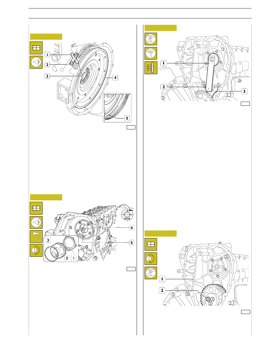
If the teeth of the ring gear mounted on the engine
flywheel, for starting the engine, are very damaged,
replace the ring gear. It must be fitted after heating
the ring gear to a temperature of approx. 200
°C.
The crankshaft has a locating peg that has to couple
with the relevant seat on the engine flywheel.
Position the flywheel (1) on the crankshaft, lubricate the
thread of the screws (2) with engine oil and screw them down.
Lock rotation with tool 99360351 (3). Lock the screws (2) in
three phases.
First phase: pre-tightening with torque wrench (4) to a torque
of 120 Nm (12 kgm).
Second and third phase: closing to angle of 60
° + 30° with tool
99395216 (1).
Figure 46
ENGINE FLYWHEEL
Fitting engine flywheel
α
NOTE
NOTE
16
SECTION 3 - INDUSTRIAL APPLICATION
72436
Figure 47
Figure 48
Figure 49
Figure 50
Position the crankshaft with the pistons 1 and 6 at the top dead
centre (T.D.C.).
This situation occurs when:
1.
The hole with reference mark (5) of the engine flywheel
(4) can be seen through the inspection window.
2.
The tool 99360612 (1), through the seat (2) of the engine
speed sensor, enters the hole (3) in the engine flywheel (4).
If this condition does not occur, turn the engine flywheel (4)
appropriately.
Remove the tool 99360612 (1).
- Fit the idle gear (1) back on and lock the screws (2) to the
required torque.
60571
- Apply the gauge 99395219 (1). Check and adjust the
position of the link rod (3) for the idle gear. Lock the screw
(2) to the required torque.
60570
Fit the camshaft (4), positioning it observing the reference
marks (
→) as shown in the figure.
Lubricate the seal (3) and fit it on the shoulder plate (2).
Mount the shoulder plate (2) with the sheet metal gasket (1)
and tighten the screws (5) to the required torque.
73843
Fitting camshaft
SECTION 3 - INDUSTRIAL APPLICATION
17
Нет комментариевНе стесняйтесь поделиться с нами вашим ценным мнением.
Текст