Engine Iveco C10/C13/C78/Cursor 13/Cursor 78. Manual — part 69
73535
Figure 62
Figure 63
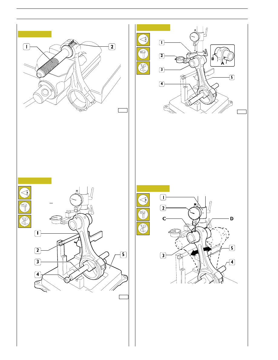
Check the bushing in the small end has not come loose and
shows no sign of scoring or seizure; replace it if it does.
The bushing (2) is removed and fitted with a suitable drift (1).
When driving it in, make absolutely sure that the holes for the
oil to pass through in the bushing and small end coincide.
Using a boring machine, rebore the bushing so as to obtain
a diameter of 50.019 — 50.035.
Checking connecting rods
61696
Checking axis alignment
Check the alignment of the axes of the connecting rods (1)
with device 99395363 (5), proceeding as follows:
Fit the connecting rod (1) on the spindle of the tool
99395363 (5) and lock it with the screw (4).
Set the spindle (3) on the V-prisms, resting the connecting
rod (1) on the stop bar (2).
Check the torsion of the connecting rod (5) by comparing
two points (A and B) of the pin (3) on the horizontal plane
of the axis of the connecting rod.
Position the mount (1) of the dial gauge (2) so that this
pre-loads by approx. 0.5 mm on the pin (3) at point A and
zero the dial gauge (2). Shift the spindle (4) with the
connecting rod (5) and compare any deviation on the
opposite side B of the pin (3): the difference between A and
B must be no greater than 0.08 mm.
Figure 64
61694
Check the bending of the connecting rod (5) by comparing
two points C and D of the pin (3) on the vertical plane of the
axis of the connecting rod.
Position the vertical mount (1) of the dial gauge (2) so that
this rests on the pin (3) at point C.
Swing the connecting rod backwards and forwards seeking
the highest position of the pin and in this condition zero the
dial gauge (2).
Shift the spindle (4) with the connecting rod (5) and repeat
the check on the highest point on the opposite side D of the
pin (3). The difference between point C and point D must be
no greater than 0.08 mm.
Figure 65
Checking bending
Bushings
34
SECTION 4 - OVERHAUL AND TECHNICAL SPECIFICATIONS

73536
74052
60614
Figure 66
Figure 67
Figure 68
The piston (1) has to be fitted on the connecting rod (2) so
that the graphic symbol (4), showing the assembly position
in the cylinder liner, and the punch marks (3) on the
connecting rod are observed as shown in the figure.
Fit the pin (2) and fasten it on the piston (1) with the split rings
(3).
To fit the piston rings (1) on the piston (2) use the pliers
99360184 (3).
The rings need to be mounted with the word ”TOP” (4)
facing upwards. Direct the ring openings so they are
staggered 120
° apart.
Mounting the piston rings
49030
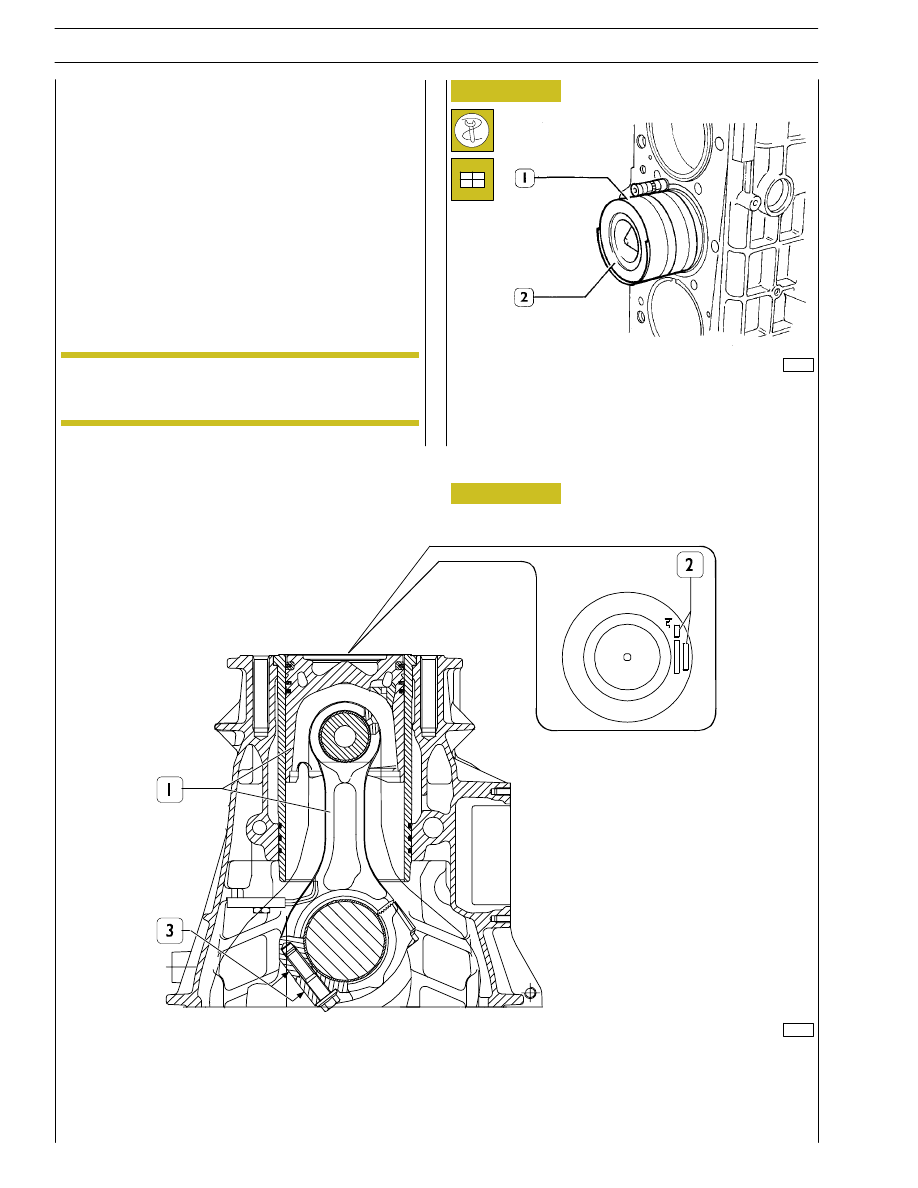
Fit the bearing shells (1), selected as described under the
heading ”Selecting the main and big end bearing shells”, on
both the connecting rod and the cap.
If reusing bearing shells that have been removed, fit them
back into their respective seats in the positions marked
during removal.
Figure 69
1
2
3
Fitting the big end bearing shells
Mounting the connecting rod — piston assembly
SECTION 4 - OVERHAUL AND TECHNICAL SPECIFICATIONS
35
60615
Fitting connecting rod - piston assemblies
in the cylinder liners
With the aid of the clamp 99360605 (1, Figure 70), fit the
connecting rod — piston assembly (2) in the cylinder liners,
according to the diagram of Figure 71, checking that:
- The openings of the piston rings are staggered 120
° apart.
- The pistons are all of the same class, A or B.
- The symbol punched on the top of the pistons faces the
engine flywheel, or the recess in the skirt of the pistons
tallies with the oil nozzles.
60616
Figure 70
Figure 71
The pistons are supplied as spares in class A and
can be fitted in class B cylinder liners.
ASSEMBLY DIAGRAM OF CONNECTING ROD — PISTON ASSEMBLY IN CYLINDER LINER
1. Connecting rod — piston assembly — 2. Area of punch marking on the top of the piston,
symbol showing assembly position and selection class — 3. Connecting rod punch mark area.
Checking piston protrusion
On completing assembly, check the protrusion of the pistons
from the cylinder liners; it must be 0.23 — 0.53 mm.
NOTE
36
SECTION 4 - OVERHAUL AND TECHNICAL SPECIFICATIONS

Checking head bearing surface on cylinder
block
Mount the connecting rod caps (1) together with the bearing
shells. Tighten the screws (2) fixing the connecting rod caps
to a torque of 50 Nm (5 kgm). Using tool 99395216 (3),
further tighten the screws with an angle of 40
°.
Remove the caps and determine the clearance by comparing
the width of the calibrated wire with the graduated scale on
the case containing the calibrated wire.
47594
47583
36159
Figure 72
Figure 73
Figure 74
Mount and secure the tool 99360264 (2) with the bracket
(4). Screw down with the device 99360261 (1) to be able to
remove the cotters (3). Take out the tool (2) and extract the
top plate (5), spring (6) and bottom plate (7).
Repeat this process on all the valves.
Turn over the cylinder head and take out the valves (8).
Check the supporting surface (1) of the head on the cylinder
block with a rule (2) and a feeler gauge (3). If you find any
deformation, level the head on a surface grinder; maximum
amount of material that can be removed 0.2 mm.
Checking crankpin assembly clearance
To measure the clearance, carry out the following
operations.
Connect the connecting rods to the relevant journals of the
crankshaft, placing a length of calibrated wire on the journals.
α
(Demonstration)
After this process, you need to check the valve
recessing and injector protrusion.
CYLINDER HEAD
Before dismounting cylinder head, check cylinder head for
hydraulic seal by proper tooling; in case of leaks not caused
by cup plugs or threaded plugs, replace cylinder head.
In case of plugs dismounting/replacement, on
mounting, apply sealant Loctite 270 on plugs.
NOTE
Dismounting the valves
Before dismounting cylinder head valves, number
them in view of their remounting in the position
observed on dismounting should they not have to
be overhauled or replaced.
NOTE
NOTE
SECTION 4 - OVERHAUL AND TECHNICAL SPECIFICATIONS
37
Нет комментариевНе стесняйтесь поделиться с нами вашим ценным мнением.
Текст