Engine Iveco C10/C13/C78/Cursor 13/Cursor 78. Manual — part 67
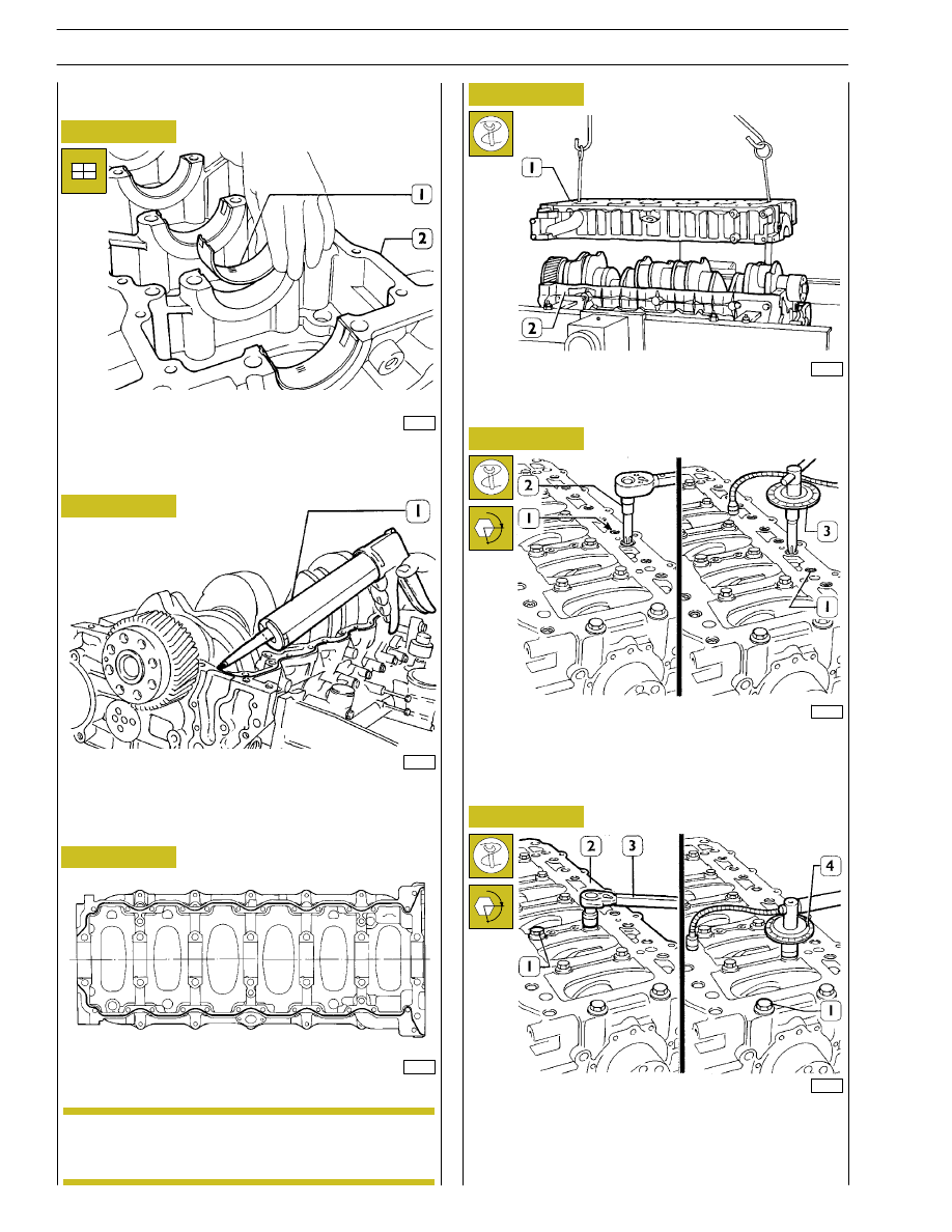
Arrange the bearing shells (1) on the main bearing housings
in the crankcase base (2).
Check the assembly clearance between the main journals of
the crankshaft and their bearings, proceeding as illustrated on
the following pages.
Using the tackle and hook 99360500 (1), mount the
crankshaft (2).
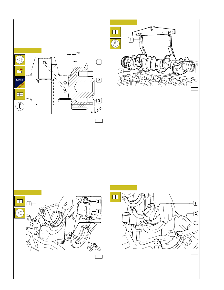
When fitting the gear (1) on the crankshaft (2), heat it for no
longer than 2 hours in an oven at a temperature of 180
°C.
After heating the gear (1), fit it on the shaft by applying a load
of 6000 N to it, positioning it at the distance shown in
Figure 32.
After cooling, the gear must have no axial movement under
a load of 29100 N.
If changing the pin (3), after fitting it on, check it protrudes
from the crankshaft as shown in the figure.
73534
47579
47578
49021
Mount the oil nozzles (2), making the grub screw match the
hole (3) on the crankcase.
Arrange the bearing shells (1) on the main bearing housings.
Replacing the timing gear
and oil pump
Check that the toothing of the gear is neither damaged nor
worn; if it is, take it out with an appropriate extractor and
replace it.
Checking main journal assembly
clearance
Figure 32
Figure 33
Figure 34
Figure 35
26
SECTION 4 - OVERHAUL AND TECHNICAL SPECIFICATIONS
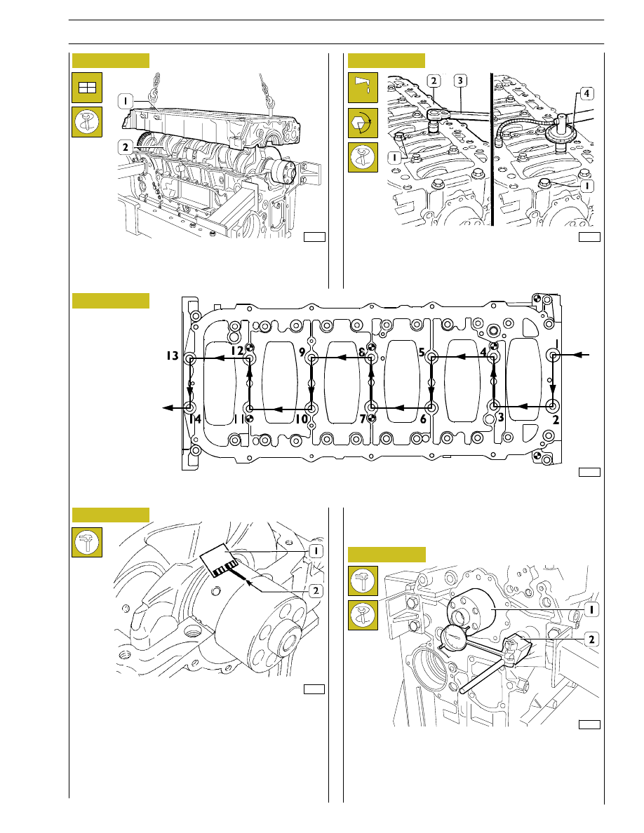
- Lubricate the internal screws (1) with UTDM oil and
tighten them with a torque wrench (3) to a torque of
120 Nm, using tool 99395216 (4), to an angle of 90
°,
following the diagram of Figure 38.
Set two journals of the crankshaft (2) parallel to the
longitudinal axis, a section of calibrated wire. Using
appropriate hooks and tackle, mount the crankcase base (1).
60559
47579
47578
47588
60593
Figure 36
Figure 37
Figure 38
Figure 39
Figure 40
- Remove the crankcase base.
The clearance between the main bearings and their journals is
measured by comparing the width taken on by the calibrated
wire (2) at the point of greatest crushing with the graduated
scale on the case (1) containing the calibrated wire.
The numbers on the scale give the clearance of the coupling
in millimetres. If you find the clearance is not as required,
replace the bearing shells and repeat the check.
FRONT SIDE
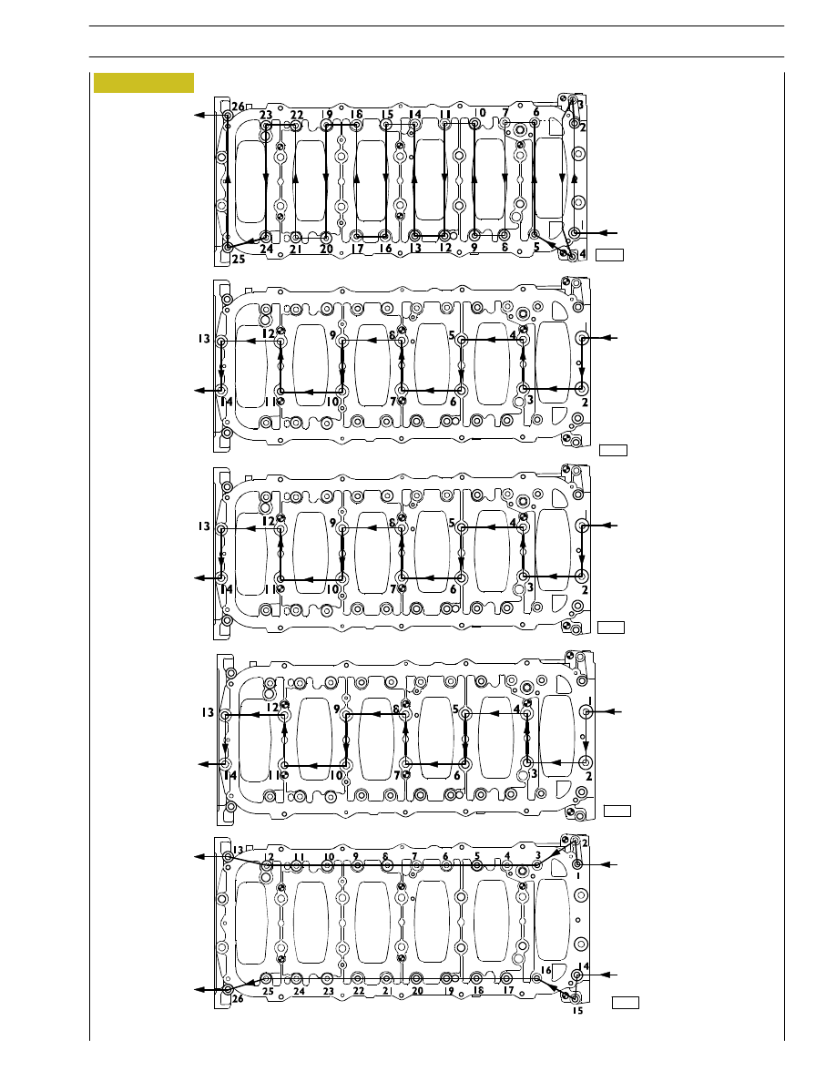
DIAGRAM OF SEQUENCE FOR TIGHTENING THE SCREWS FIXING THE BOTTOM CRANKCASE BASE
TO THE CRANKCASE
Checking crankshaft end float
α
End float is checked by placing a magnetic dial gauge (2) on
the crankshaft (1), as shown in the figure. If the value obtained
is higher than specified, replace the rear thrust half-bearings
and repeat this check.
SECTION 4 - OVERHAUL AND TECHNICAL SPECIFICATIONS
27
47595
47596
Figure 41
Figure 42
Place the half-bearings (1) on the main bearings in the
underblock (2).
By means of suitable equipment (1) apply silicone LOCTITE
5970 IVECO No. 2992644 to the block, as shown in the
figure.
Sealant application diagram
Fit the underblock within 10’ of the application of
the sealant.
Figure 43
49021
47581
Figure 44
Figure 45
Fit the sub-engine block and use a dynamometric wrench (2)
to tighten the outer hexagonal-grooved screws (1) to 25 Nm
according to the diagrams on the following page.
Fit the underblock by means of a suitable hoist and hooks (1).
49022
Figure 46
Close the inner screws (1) to 140 Nm torque by means of
a dynamometric wrench (3), then with two further angular
phases 60
° + 60°, using tool 99395216 (4). Tighten again the
outer screws (1, Figure 45) with 90
° angular closing, using
tool 99395215 (3, Figure 45).
α
α
47579
ASSEMBLING
THE
ENGINE
ON
THE
BENCH
NOTE
28
SECTION 4 - OVERHAUL AND TECHNICAL SPECIFICATIONS
60593
FRONT SIDE
stage 4:
angle
inner
screws
(45º)
60592
60594
Figure 47
stage 1:
pretightening
outer screws
(30 Nm)
FRONT SIDE
FRONT SIDE
FRONT SIDE
stage 2:
pretightenig
inner screws
(120 Nm)
stage 5:
angle
outer
screws
(60º)
FRONT SIDE
stage 3:
angle
inner
screws
(90º)
60593
60593
DIAGRAM OF TIGHTENING SEQUENCE OF CRANKCASE BASE FIXING SCREWS
SECTION 4 - OVERHAUL AND TECHNICAL SPECIFICATIONS
29
Нет комментариевНе стесняйтесь поделиться с нами вашим ценным мнением.
Текст