Engine Iveco C10/C13/C78/Cursor 13/Cursor 78. Manual — part 51
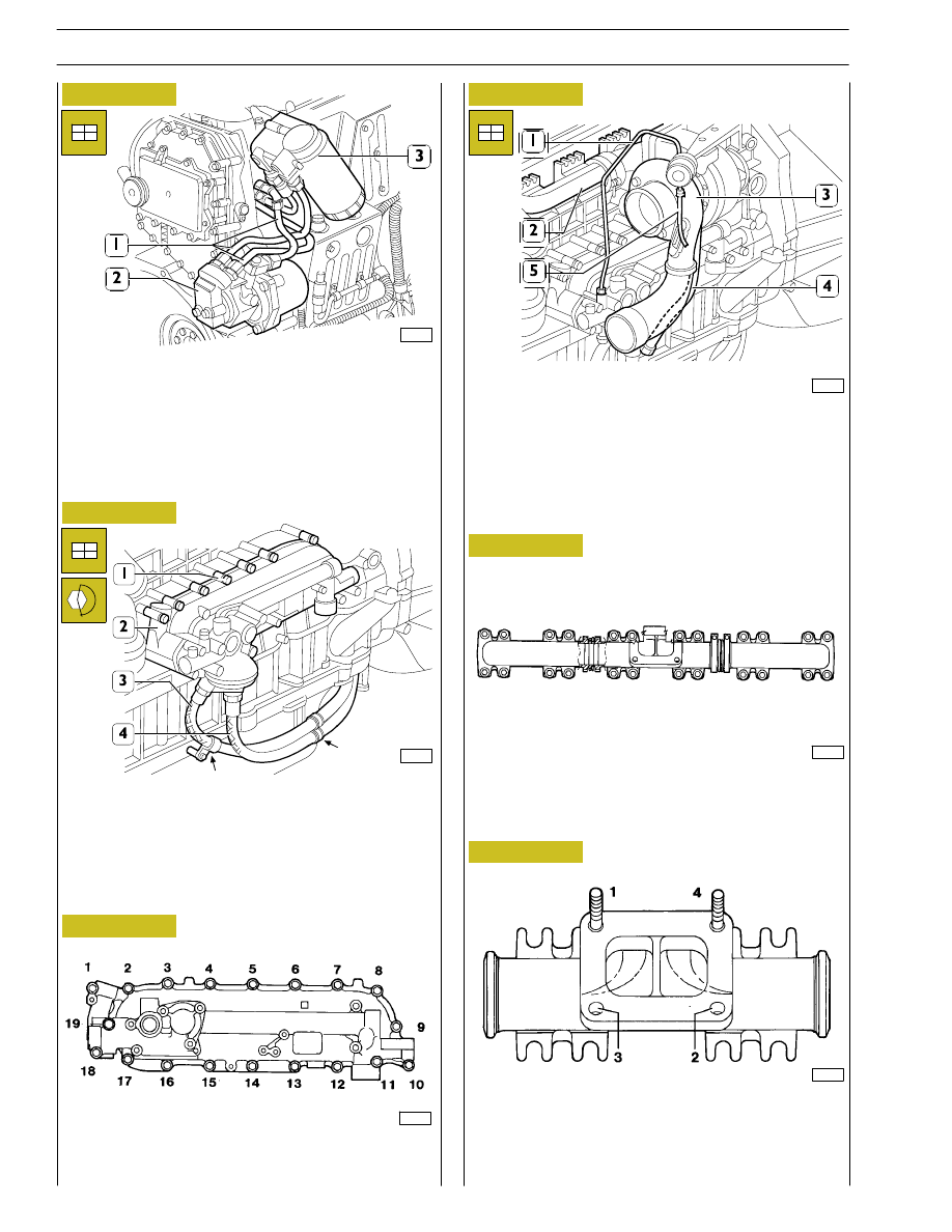
Fit, with the respective gaskets.
-
the fuel pump (2);
-
fuel filter unit (3) and pipes (1);
-
connect the pipes (1) to the fuel pump (2).
99273
Figure 79
Figure 80
Figure 81
Figure 82
For all types except:
F3AE0684D*B003 and F3AE0684E*B002
Mount the cooler (2) with the relevant seal and tighten the
fixing screws (1) to the prescribed torque.
Tighten the screws (
←) fixing the clamps retaining the pipes
(3 and 4) to the spacer.
Mount the following with new seals:
-
exhaust manifold (2);
-
turbocharger (3);
-
oil pipe (1 and 4);
-
pipe to the actuator (5).
99258
455361
DIAGRAM OF HEAT EXCHANGER FIXING SCREWS
TIGHTENING SEQUENCE
99274
Figure 83
Figure 84
DIAGRAM OF EXHAUST MANIFOLD FIXING SCREWS
TIGHTENING SEQUENCE
DIAGRAM OF TURBOCHARGER FIXING SCREWS AND
NUTS TIGHTENING SEQUENCE
SEQUENCE: Preliminary tightening
4 - 3 - 1 - 2
Tightening
1 - 4 - 2 - 3
45359
1
8
6
3
2
7
6
3
4
7
6
3
2
7
5
4
8
5
2
8
5
4
1
1
45360
26
SECTION 3 - INDUSTRIAL APPLICATION
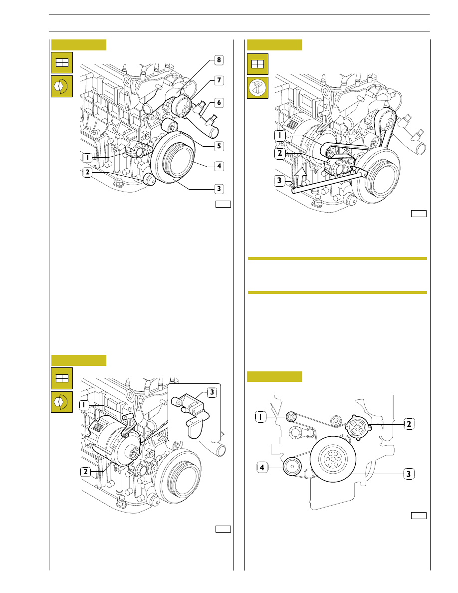
Figure 85
Figure 86
Fit, with the following parts:
-
automatic tightener support (1);
-
automatic tightener (2);
-
damper flywheel (3) and pulley beneath;
-
fixed tightener (5);
-
water pump (7);
-
the pulley (4);
-
pipe comprehensive of coolant (6);
-
thermostat assembly (8).
Figure 87
Mount the following, tightening the screws to the prescribed
torque:
-
the supports (1 and 3);
-
alternator (2).
Using a suitable tool (3), work in the direction of the arrow on
the tightener (2) and mount the belt (1).
The tighteners are automatic, so there are no other
adjustments after assembly.
99360
99256
99359
DIAGRAM FOR FITTING BELT DRIVING FAN - WATER
PUMP - ALTERNATOR
1. Alternator - 2. Water pump - 3. Crankshaft -
4. Compressor.
Figure 88
101701
NOTE
SECTION 3 - INDUSTRIAL APPLICATION
27
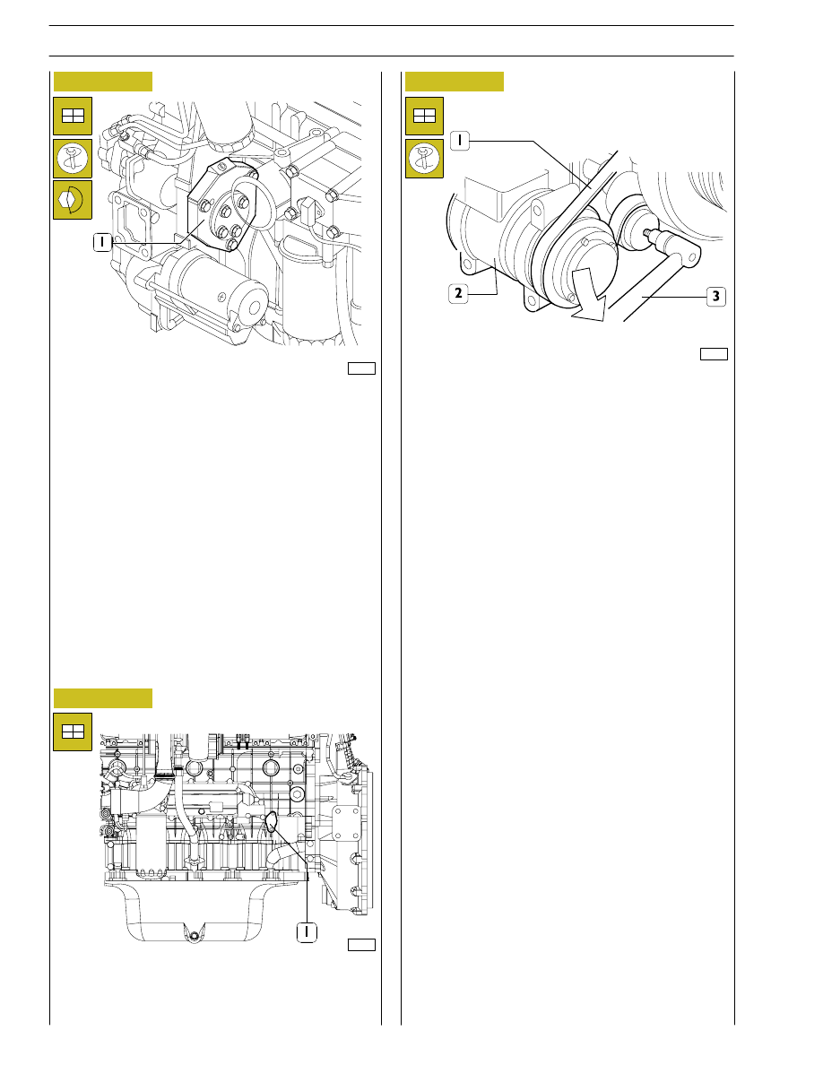
Figure 89
Figure 90
Figure 91
Fit the engine support together with the air-conditioner
compressor (2).
Using a suitable tool (3), work in the direction of the arrow and
mount the belt (1).
Connect the engine electric cable to the sensors and control
unit.
Refill the engine with lubricating oil of the prescribed grade and
quantity.
Fit the arm 99360585 onto the engine lifting hooks and hook
the arm onto the hoist.
Take out the screws fixing the brackets 99361036 to the
rotary stand. Lift the engine and remove the above-mentioned
brackets from it.
Complete engine assembly with the following parts, tightening
the fixing screws or nuts to the prescribed torque:
-
mount the drive (1);
-
mount the engine supports;
-
mount the oil pressure adjuster valve (1).
99254
99253
99357
28
SECTION 3 - INDUSTRIAL APPLICATION
PART TWO -
ELECTRICAL EQUIPMENT
SECTION 3 - INDUSTRIAL APPLICATION
29
Нет комментариевНе стесняйтесь поделиться с нами вашим ценным мнением.
Текст