Engine Iveco C10/C13/C78/Cursor 13/Cursor 78. Manual — part 50
22
SECTION 3 - INDUSTRIAL APPLICATION
Clockwise
start-up
and rotation
Adjusting
cylinder
valve no.
Adjusting
clearance
of cylinder
valve no.
Adjusting
pre-loading
of cylinder
injector no.
1 and 6 at TDC
6
1
5
120º
3
4
1
120º
5
2
4
120º
1
6
2
120º
4
3
6
120º
2
5
3
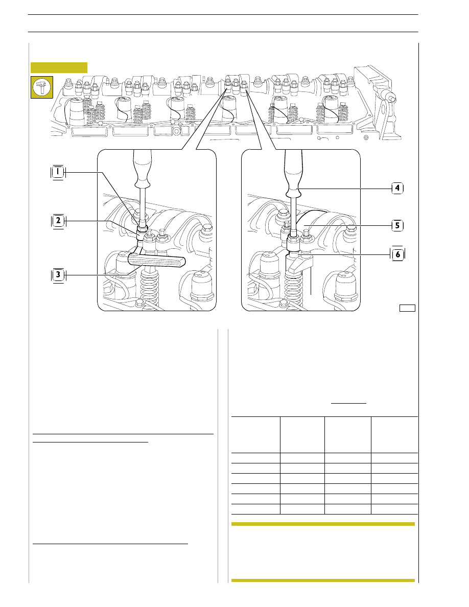
- using an appropriate wrench (4), loosen the adjustment
screw
until
the
pumping
element
is
at
the
end-of-stroke;
- tighten the adjustment screw, with a dynamometric
wrench, to 5 Nm tightening torque (0.5 kgm);
- untighten the adjustment screw by 1/2 to 3/4 rotation;
- tighten the locking nut.
FIRING ORDER 1-4-2-6-3-5
The adjustment of clearance between the rockers and rods
controlling the intake and exhaust valves, as well as the
adjustment of pre-loading of the rockers controlling pump
injectors, must be carried out carefully.
Take the cylinder where clearance must be adjusted to the
bursting phase; its valves are closed while balancing the
symmetric cylinder valves.
Symmetric cylinders are 1-6, 2-5 and 3-4.
In order to properly operate, follow these instructions and
data specified on the table.
Adjustment of clearance between the rockers and rods
controlling intake and exhaust valves:
- use a polygonal wrench to slacken the locking nut (1) of
the rocker arm adjusting screw (2).
- insert the thickness gauge blade (3);
- tighten or untighten the adjustment screw with the
appropriate wrench;
- make sure that the gauge blade (3) can slide with a slight
friction;
- lock the nut (1), by blocking the adjustment screw.
Pre-loading of rockers controlling pump injectors:
- using a polygonal wrench, loosen the nut locking the
rocker adjustment screw (5) controlling the pump
injector (6);
ADJUSTMENT OF INTAKE, EXHAUST AND INJECTION ROCKERS
In order to properly carry out the above-mentioned
adjustments, follow the sequence specified in the
table, checking the exact position in each rotation
phase by means of pin 99360612, to be inserted in
the 11
th
hole in each of the three sectors with 18
holes each.
Figure 66
99272
Intake and exhaust rocker play adjustment and pre-loading of rockers controlling pump injectors
NOTE

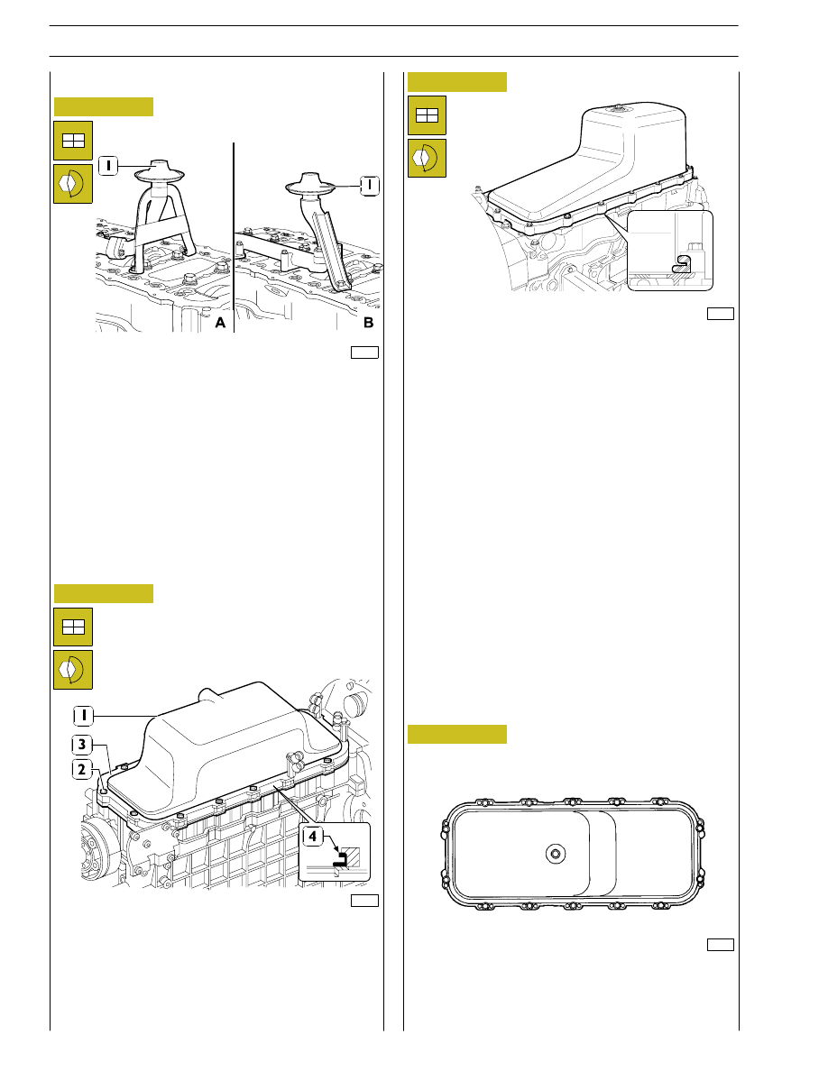
Apply silicone LOCTITE 5970 IVECO No. 2992644 on the
blow-by case and form a string (2) of
∅ 1,5 ±,
as shown
in the figure.
Fit the blow-by case (1) within 10’ from sealer
application.
Fit the cover (3) and tighten the fastening screws (2) to the
prescribed torque.
The filter (5) operation is unidirectional, therefore
it must be assembled with the two sight supports
as illustrated in the figure.
Fit the distribution cover (1).
Figure 67
Figure 68
DIAGRAM OF ROCKER ARM CAP FIXING SCREWS
TIGHTENING SEQUENCE
Apply silicone LOCTITE 5970 IVECO n˚ 2992644
on the blow-by case (7) surface of engines fitted
with P.T.O. according to the procedure described
in the following figure.
85480
85481
0.5
0.2
.
The valve rocker arm cover fastening screws (1)
shall be tightened according to the sequence shown
in Figure 68.
Fit the blow-by case (7) and its gasket and then tighten the
screws (8) to the prescribed torque.
Install the filter (5) and the gaskets (4 and 6).
45363
17
14
13
1
4
5
8
18
19
20
16
15
12
2
3
6
7
11
10
9
Figure 69
NOTE
NOTE
NOTE
NOTE
SECTION 3 - INDUSTRIAL APPLICATION
23
ENGINE COMPLETION
Place gasket (4) on oil sump (1), position spacer (3) and fit the
sump on the engine base by tightening screws (2) to the
specified torque, by complying with the tightening sequence
shown in Figure 73.
For types:
F3AE0684D*B001 - F3AE0684G*B003 -
F3AE0684D*B003.
For types: F3AE0684E*B002 - F3AE0684J*B902.
Fit the suction strainer (1) and tighten the fixing screws to the
prescribed torque.
A. for types: F3AE0684E*B002 - F3AE0684J*B902.
B. for types: F3AE0684D*B001 - F3AE0684G*B003
F3AE0684D*B003.
Figure 70
Figure 71
99367
Figure 72
Figure 73
99268
81871
DIAGRAM OF ENGINE OIL SUMP FIXING SCREWS
TIGHTENING SEQUENCE
1
8
12
11
10
3
9
13
14
4
5
6
7
2
45362
24
SECTION 3 - INDUSTRIAL APPLICATION
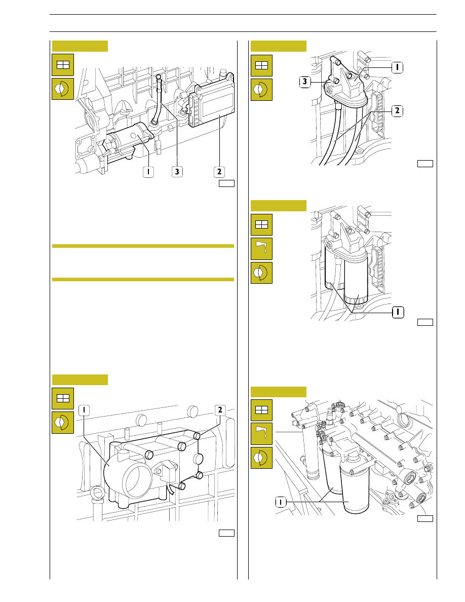
Figure 74
Fit the intake manifold (1) and tighten the fixing screws (2) to the
prescribed torque.
Fit the oil filters (1) on the relevant supports as follows:
-
oil the seals;
-
screw the filters down for the seals to make contact with
the supporting bases;
-
tighten the filters to a torque of 35 to 40 Nm.
Figure 75
Figure 76
Figure 77
Mount the support (1) and tighten the fixing screws (3).
Connect the oil pipes (2) to the support (1) tightening the
fittings to the prescribed torque.
99264
99362
Tightening the fixing screws to the prescribed torque, mount:
-
the starter motor (1);
-
the control unit (2) and its support;
-
the oil dipstick (3) in the crankcase.
Check the state of the flexible elements of the
control unit support and change them if they have
deteriorated.
99263
Figure 78
Solely for types:
F3AE0684D*B003 and F3AE0684E*B002
Mount the oil filters (1) on the support as follows:
-
oil the seal;
-
screw the filters down for the seals to make contact with
the supporting bases;
-
tighten the filters to a torque of 35 to 40 Nm.
99363
101960
NOTE
SECTION 3 - INDUSTRIAL APPLICATION
25
Нет комментариевНе стесняйтесь поделиться с нами вашим ценным мнением.
Текст