Engine Iveco C10/C13/C78/Cursor 13/Cursor 78. Manual — part 127
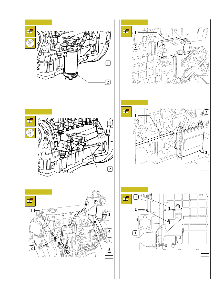
Figure 10
Figure 11
Figure 12
Figure 13
Figure 14
Unscrew the oil filter (1) by tool 99360314 (2).
Unscrew the screws (1) and remove the entire heat
exchanger (2).
Take out the screws (2) and remove the intake manifold (1).
107940
107941
107942
Disconnect fuel lines (1) from cylinder head; (2) and supply
pump.
Remove screws (5) and support (6) complete with fuel filter
(3) and sedimentation filter (4).
107943
107944
Disconnect fuel line (1) from central unit (3).
Remove screws (2) and disconnect central unit (3).
Remove screws (2) and disconnect power takeoff (1)
complete with supply pump (3).
To go on with the engine disassembly as described for the
industrial/agricultural applications engines.
Figure 15
107945
SECTION 2 - APPLICATION G-DRIVE
25
Handle all parts extremely carefully. Never get your
hands or fingers between pieces.
Wear the required safety clothing such as goggles,
gloves and safety shoes.
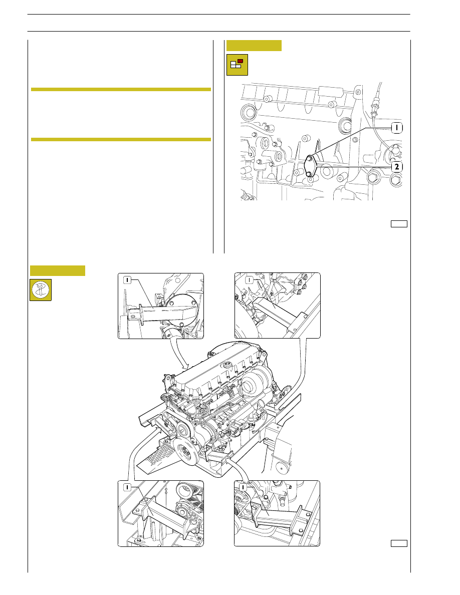
Remove screws (1) and remove oil pressure adjustment valve
(2).
Figure 16
Figure 17
F2B engine assembly
To assembly again the engine inverting the described
operations for the disassembly.
NOTE
107970
107971
Secure the engine to the rotary stand with the brackets 99361036 (1).
To release the lubrication oil from the pan.
F3B engine disassembly
Protect the electric parts before doing any washing with
high-pressure jets.
Here are described and illustrated the engine disassembly
operations which are different from the operations for the
industrial application engines.
Before securing the engine on the rotary stand, remove:
-
the electric engine cable (1) by disconnecting it from the
control unit and all the sensors/transmitters to which it is
connected.
-
Remove the engine supports.
26
SECTION 2 - APPLICATION G-DRIVE
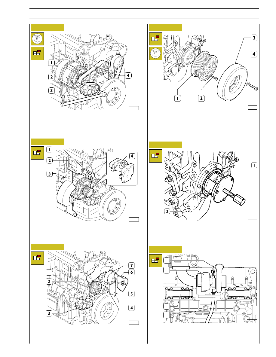
Figure 18
Figure 19
Figure 20
Figure 21
Figure 22
107903
Remove guard (3).
Remove retaining screws and remove alternator (2) from
bracket (1) and from support (4), then remove the latter from
block.
Use specific tool (3) to operate on belt tensioner (2) in
direction of arrow, remove water pump alternator and
ventilator control belt (1). Remove screws and disconnect
electromagnetic ventilator coupling (4).
107904
87204
107889
Remove thermostat (1), ventilator support (2), automatic belt
tensioner (3), fixed belt tensioner (4), pipeline (5),guard (6),
water pump (7).
Block the flywheel rotation with tool 99360351.
Remove screws (4), then disassemble damper flywheel (3).
Remove the screws (2) and the pulley (1).
45254
Install extractor 99340051 (2) and remove the seal gaskets
(1). Unscrew the screws and remove the cover.
Disconnect all electric connections and sensors.
Figure 23
107890
Disconnect oil pipes (1 and 4) of turbo compressor (2).
Disconnect turbo compressor (2) from exhaust manifold (3).
1
2
3
4
SECTION 2 - APPLICATION G-DRIVE
27
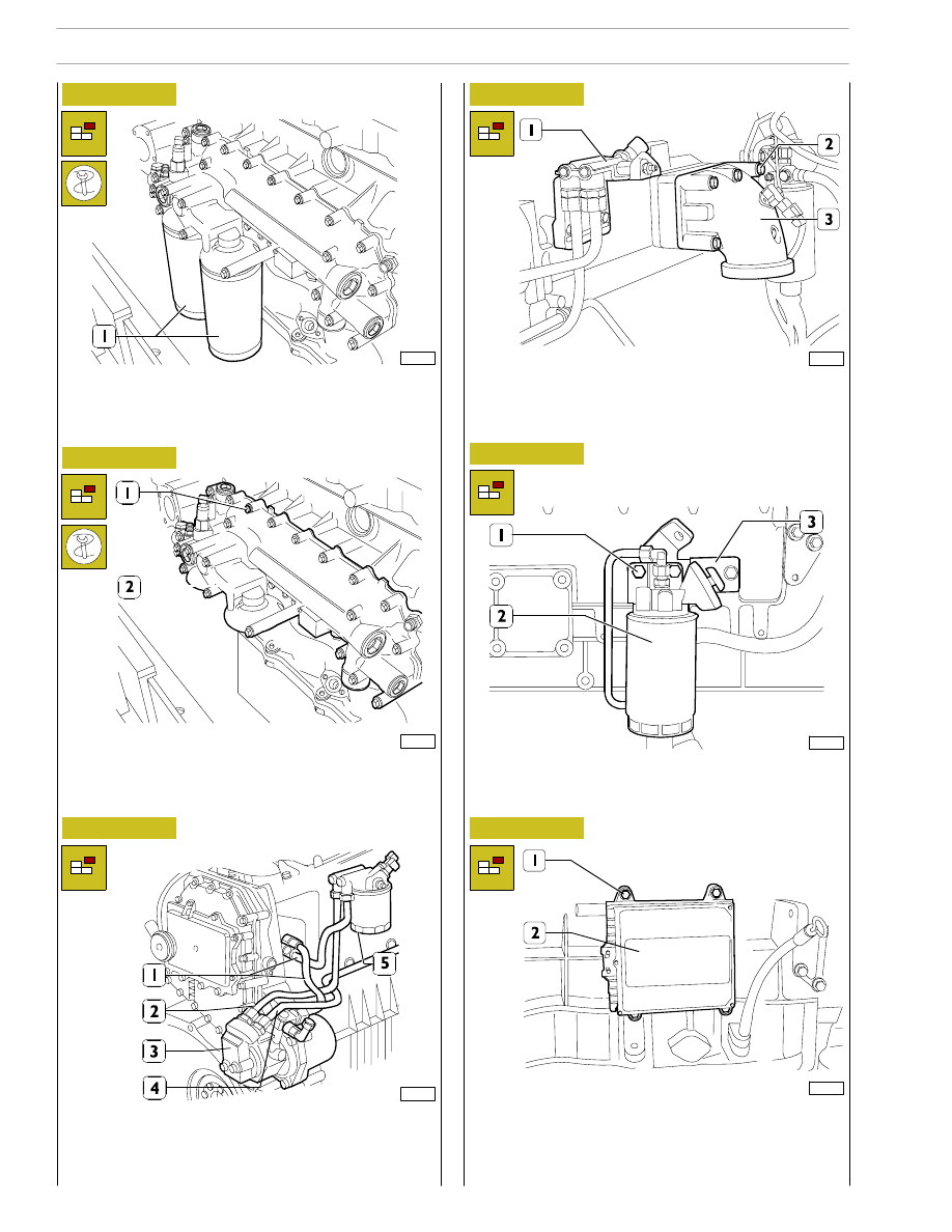
Figure 24
Figure 25
Figure 26
Figure 27
Figure 28
Unscrew the oil filter (1) by tool 99360314.
Remove retaining screws and support (1) of fuel filter.
Remove screws (2) and remove intake manifold (3).
107972
107973
107974
107975
107976
Remove screws (1) and bracket (3) supporting sedimentation
tank prefilter (2).
Remove screws (1) and disconnect ECU (2).
Figure 29
107977
Unscrew the screws (1) and remove the heat exchanger (2).
Disconnect the fuel pipes (1 and 4) from the fuel pump (2).
Remove supply pump (3) and fuel filter (5).
28
SECTION 2 - APPLICATION G-DRIVE
Нет комментариевНе стесняйтесь поделиться с нами вашим ценным мнением.
Текст