Engine Iveco C10/C13/C78/Cursor 13/Cursor 78. Manual — part 107
47957
71716
Figure 61
Figure 62
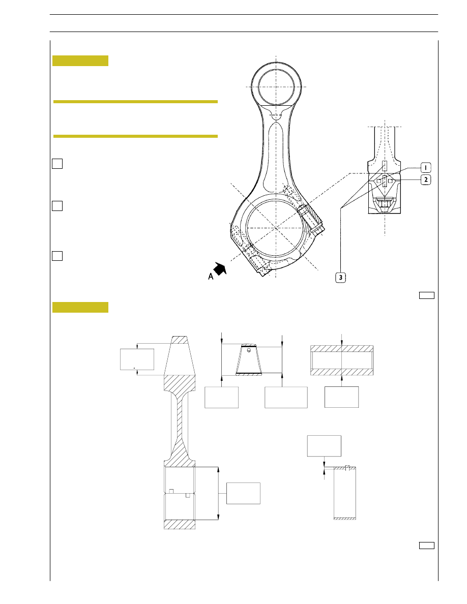
MAIN DATA OF THE BUSHING, CONNECTING ROD, PIN AND BEARING SHELLS
* Measurement to be made after driving in the bushing.
Connecting rod punch markings
Letter indicating the class of weight:
A
=
4741 to 4780 g.
B
=
4781 to 4820 g.
C
=
4821 to 4860 g.
Number indicating the selection of the diameter
of the big end bearing seat:
1
=
94.000 to 94.010 mm
2
=
94.011 to 94.020 mm
3
=
94.021 to 94.030 mm
Number indicating the selection of diameter
for the big end bearing housing:
1
2
3
Punched on the big end of the connecting rod are the data
relating to the section in classes relating to the connecting
rod seats and the weights.
On assembling the connecting rods, check
they are all of the same class of weight.
VIEW FROM “A”
54.000
54.030
54.085
54.110
50.019*
50.035*
49.994
50.000
1.970
2.000
87.000
87.030
Connecting rod
NOTE
SECTION 4 - OVERHAUL AND TECHNICAL SPECIFICATIONS
33
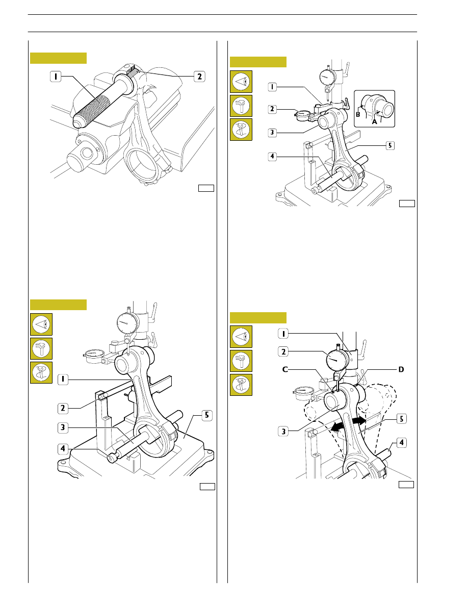
Check the torsion of the connecting rod (5) by comparing
two points (A and B) of the pin (3) on the horizontal plane
of the axis of the connecting rod.
Position the mount (1) of the dial gauge (2) so that this
pre-loads by approx. 0.5 mm on the pin (3) at point A and
zero the dial gauge (2). Shift the spindle (4) with the
connecting rod (5) and compare any deviation on the
opposite side B of the pin (3): the difference between A and
B must be no greater than 0.08 mm.
Check the bending of the connecting rod (5) by comparing
two points C and D of the pin (3) on the vertical plane of the
axis of the connecting rod.
Position the vertical mount (1) of the dial gauge (2) so that this
rests on the pin (3) at point C.
Swing the connecting rod backwards and forwards seeking the
highest position of the pin and in this condition zero the dial
gauge (2). Shift the spindle (4) with the connecting rod (5) and
repeat the check on the highest point on the opposite side D
of the pin (3). The difference between point C and point D
must be no greater than 0.08 mm.
61695
61696
Checking axis alignment
Check the alignment of the axes of the connecting rods (1)
with device 99395363 (5), proceeding as follows:
Fit the connecting rod (1) on the spindle of the tool
99395363 (5) and lock it with the screw (4).
Set the spindle (3) on the V-prisms, resting the connecting
rod (1) on the stop bar (2).
Figure 63
Figure 64
Figure 65
Checking torsion
61694
Checking bending
Checking connecting rods
73535
Check the bushing in the small end has not come loose and
shows no sign of scoring or seizure; replace it if it does.
The bushing (2) is removed and fitted with a suitable drift (1).
When driving it in, make absolutely sure that the holes for the
oil to pass through in the bushing and small end coincide.
Using a boring machine, rebore the bushing so as to obtain
a diameter of 54.019 — 54.035.
Figure 66
Bushings
34
SECTION 4 - OVERHAUL AND TECHNICAL SPECIFICATIONS
SECTION 4 - OVERHAUL AND TECHNICAL SPECIFICATIONS
35
1
2
3
73536
74052
60614
49030
Figure 67
Figure 68
Figure 69
Figure 70
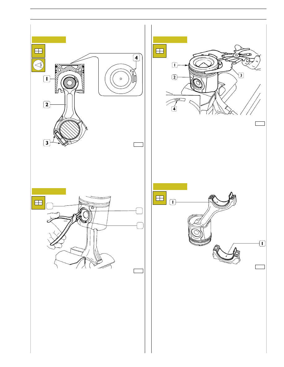
The piston (1) has to be fitted on the connecting rod (2) so
that the graphic symbol (4), showing the assembly position
in the cylinder liner, and the punch marks (3) on the
connecting rod are observed as shown in the figure.
Fit the pin (2) and fasten it on the piston (1) with the split rings
(3).
To fit the piston rings (1) on the piston (2) use the pliers
99360184 (3).
The rings need to be mounted with the word ”TOP” (4)
facing upwards. Direct the ring openings so they are
staggered 120
° apart.
Fit the bearing shells (1), selected as described under the
heading ”Selecting the main and big end bearing shells”, on
both the connecting rod and the cap.
If reusing bearing shells that have been removed, fit them
back into their respective seats in the positions marked
during removal.
Mounting the connecting rod — piston assembly
Mounting the piston rings
Fitting the big end bearing shells
60616
Figure 71
Figure 72
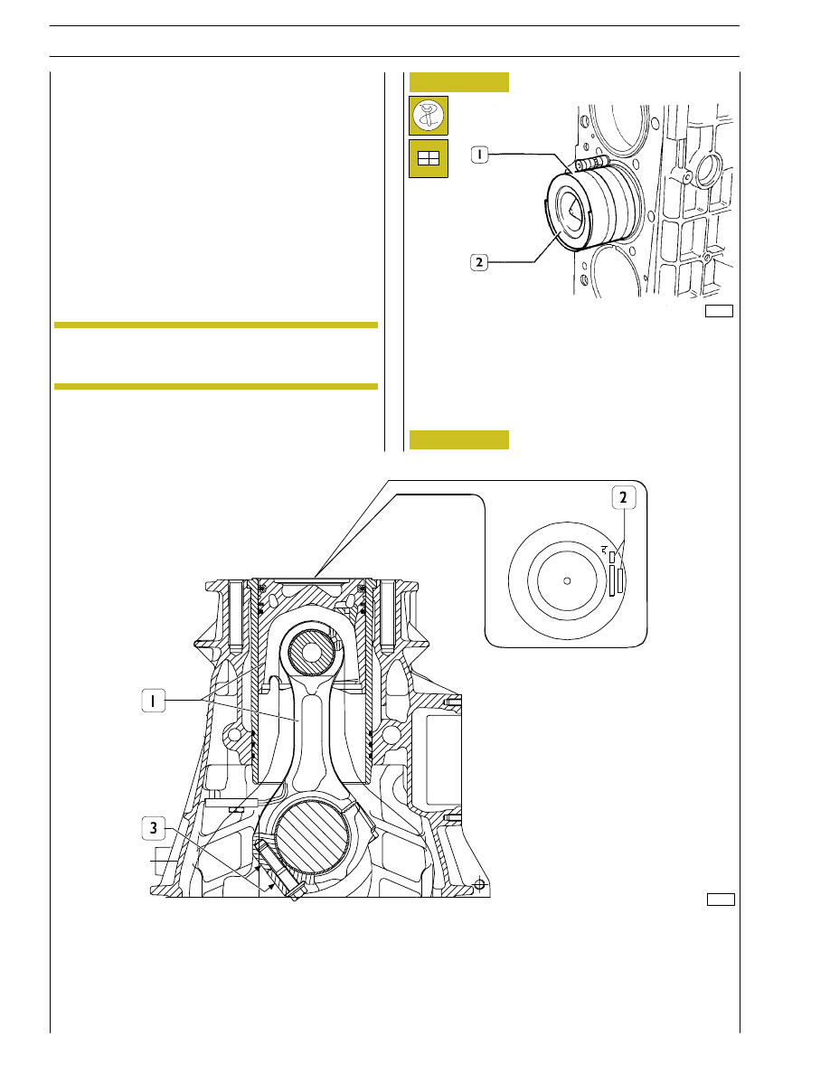
ASSEMBLY DIAGRAM OF CONNECTING ROD — PISTON ASSEMBLY IN CYLINDER LINER
1. Connecting rod — piston assembly — 2. Area of punch marking on the top of the piston,
symbol showing assembly position and selection class — 3. Connecting rod punch mark area
Fitting connecting rod - piston assemblies in
the cylinder liners
With the aid of the clamp 99360605 (1, Figure 71), fit the
connecting rod — piston assembly (2) in the cylinder liners,
according to the diagram of Figure 72, checking that:
- The openings of the piston rings are staggered 120
°
apart.
- The pistons are all of the same class, A or B.
- The symbol punched on the top of the pistons faces the
engine flywheel, or the recess in the skirt of the pistons
tallies with the oil nozzles.
The pistons are supplied as spares in class A and can
be fitted in class B cylinder liners.
60615
Checking piston protrusion
On completing assembly, check the protrusion of the pistons
from the cylinder liners; it must be 0.12 — 0.42 mm.
NOTE
36
SECTION 4 - OVERHAUL AND TECHNICAL SPECIFICATIONS
Нет комментариевНе стесняйтесь поделиться с нами вашим ценным мнением.
Текст