Engine Iveco C10/C13/C78/Cursor 13/Cursor 78. Manual — part 93
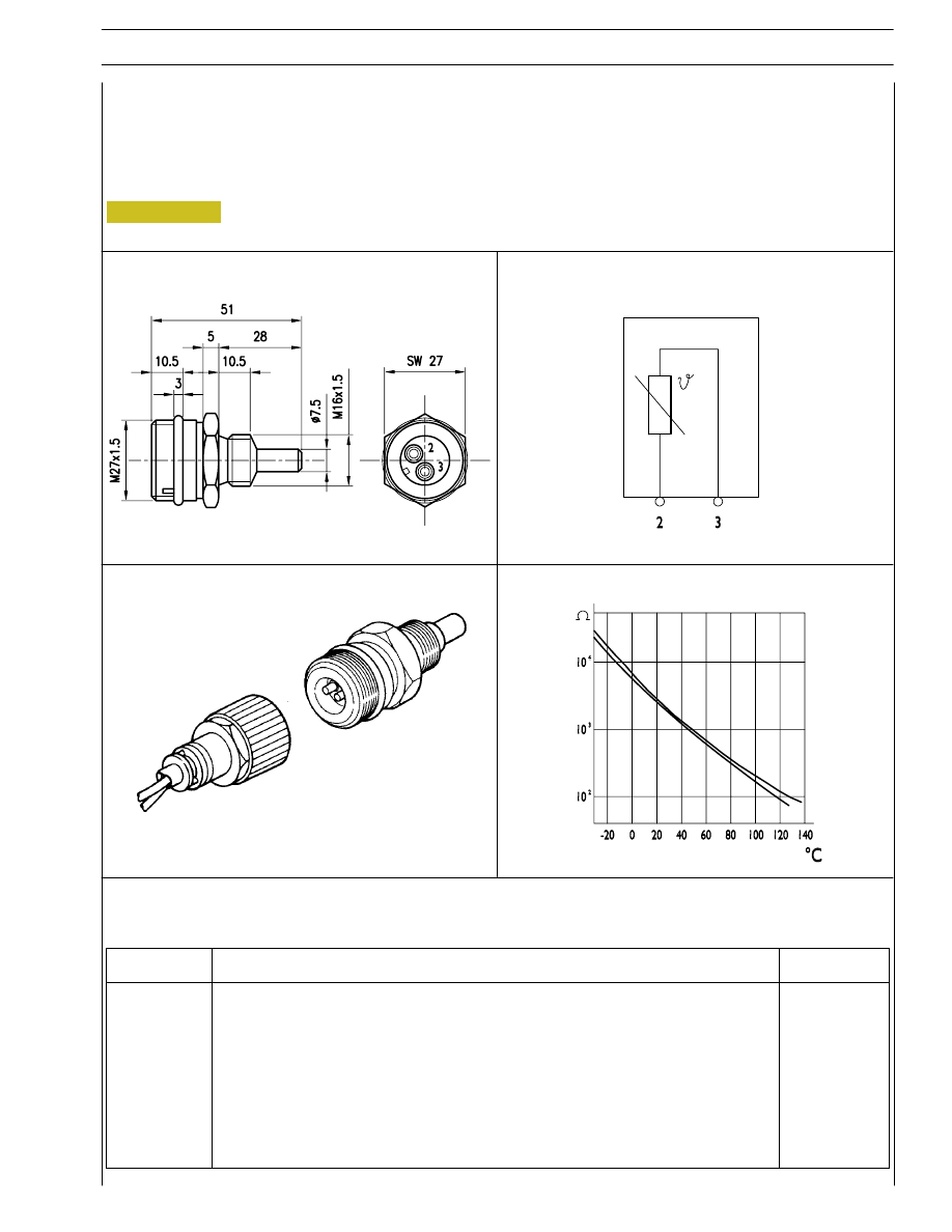
Figure 95
Fuel temperature sensor
Specifications
Supplier
BOSCH
Max. tightening torque
35 Nm
TECNICAL VIEW
8527
8528
WIRING DIAGRAM
PERSPECTIVE VIEW
8529
8530
RESISTANCE TREND
SECTION 3 - INDUSTRIAL APPLICATION
39
Pin
Function
Cable colour
2
To pin 6 of EDC control unit
–
3
To pin 11 of EDC control unit
–
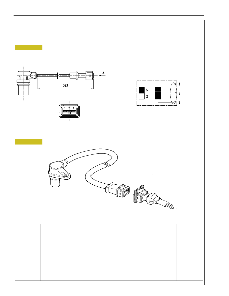
Figure 96
Flywheel pulse transmitter
Specifications
Supplier
BOSCH
Max. tightening torque
8
± 2 Nm
TECNICAL VIEW
8518
8519
WIRING DIAGRAM
Figure 97
8520
40
SECTION 3 - INDUSTRIAL APPLICATION
Pin
Function
Cable colour
1
To pin 1 of EDC control unit
–
2
To pin 13 of EDC control unit
–
3
Screens
–
TECHNICAL VIEW
WIRING DIAGRAM
PERSPECTIVE VIEW
8520
REFERENCE ON SOUND WHEEL
000606t
SECTION 3 - INDUSTRIAL APPLICATION
41
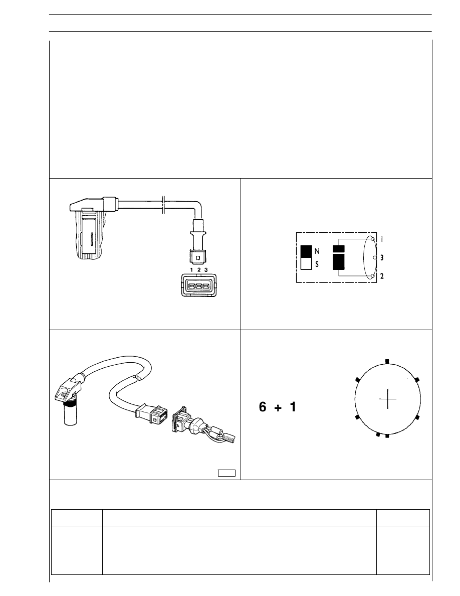
Distribution pulse transmitter
Features
Vendor
BOSCH
Torque
8
± 2 Nm
Resistance
880
÷ 920 Ω
This induction type sensor located on the camshaft generates signals obtained from the magnetic flow lines that close through the
6 plus 1 phase teeth of a sound wheel mounted on the shaft.
The electronic center uses the signal generated by this sensor as an injection step signal.
Though electrically identical to engine rpm sensor mounted in the camshaft in is NOT interchangeable with it as it cable is shorter
and it features a larger diameter.
This sensor’s air gap is NOT ADJUSTABLE.
Connector
Function
Cable colour
1
To EDC center pin A 2
–
2
To EDC center pin A 14
–
3
Shields
–
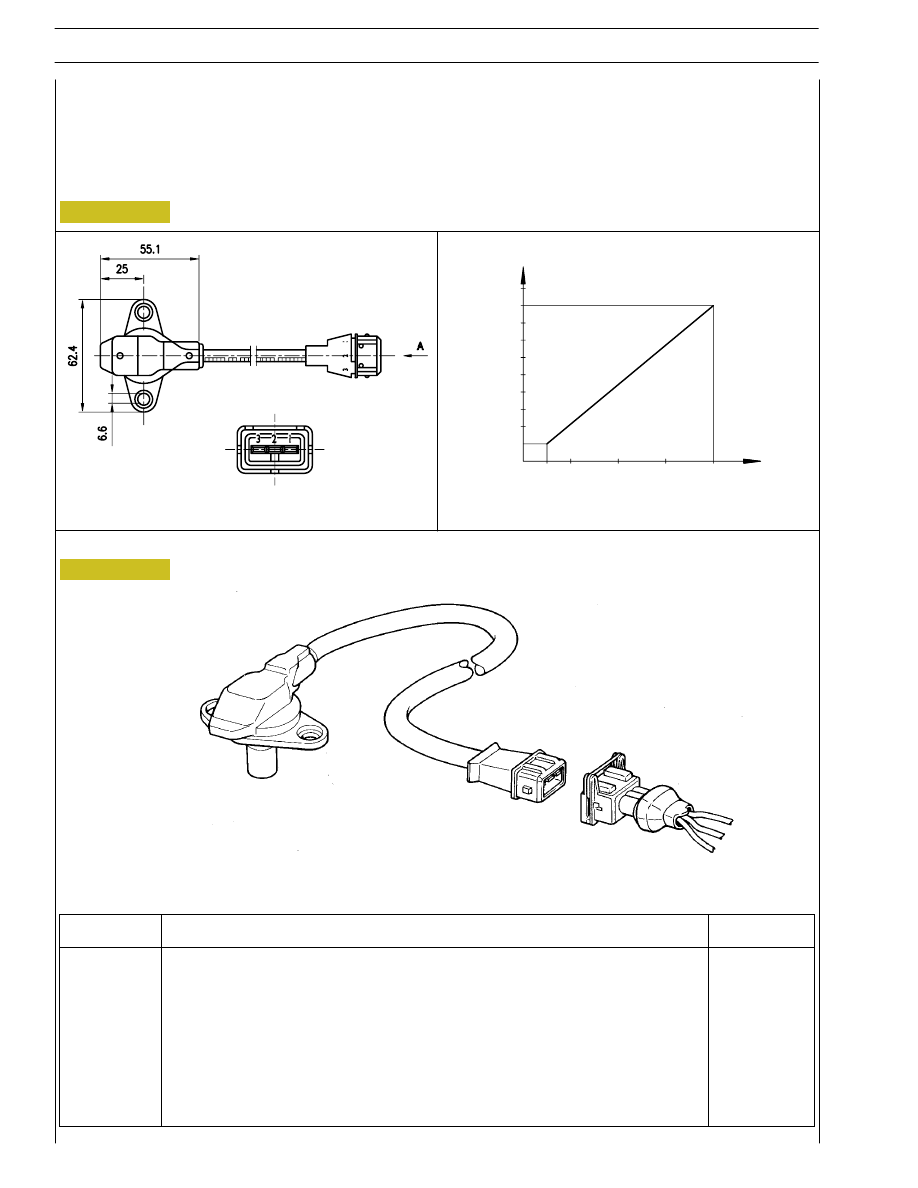
Figure 98
Boosting pressure transmitter
Specifications
Supplier
BOSCH
Code
B 281022 018
Operating pressure field
50
÷ 400 kPa
Max. tightening torque
10 Nm
Figure 99
TECNICAL VIEW
8521
8522
MAX ABSOLUTE PRESSURE SPECIFICATIONS 600 KPA
30 100
200
300
400
P
[kPa]
1
2
3
4
5
U
[V]
A
PERSPECTIVE VIEW
8523
42
SECTION 3 - INDUSTRIAL APPLICATION
Pin
Function
Cable colour
1
To pin 12 of EDC control unit
–
2
To pin 23 of EDC control unit
–
3
To pin 17 of EDC control unit
–
Нет комментариевНе стесняйтесь поделиться с нами вашим ценным мнением.
Текст