Engine Iveco C10/C13/C78/Cursor 13/Cursor 78. Manual — part 92
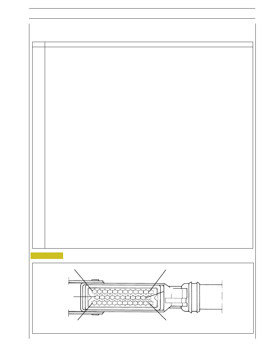
EDC control unit PIN-OUT
Connector “B” (Frame area)
Figure 91
SECTION 3 - INDUSTRIAL APPLICATION
35
Pin
Functions
1 - Negative direct from battery / blink button — code
2 - Negative direct from battery / blink button — code
3 - Positive from main remote switch
4 - Positive from main remote switch
5 - Signal for electronic rev. counter (if available)
6 - Negative for EDC / blink button — code warning light (if available)
7 - CAN line for Multiplex electric system architecture
8 - ---
9 - Engine phase signal for diagnosis connector
10 - Negative for pre-post heating remote switch engagement
11 - CAN - L line for interconnection of the CAN line with control units (if any) available with the application
12 - CAN - H line for interconnection of the CAN line with control units (if any) available with the application
13 - K line for diagnosis connector
14 - ---
15 - Key controlled supply positive
16 - Accelerator pedal position sensor supply
17 - Negative from idler switch
18 - Negative for warning light pre — post heating
19 - ---
20 - Positive from N.C. clutch switch (if available)
21 - Function “RESUME” Cruise Control (if available)
22 - Positive from speed reducer switch (if available)
23 - Accelerator pedal position signal sensor
24 - L line for diagnosis connector
25 - Negative for accelerator pedal, multiple-state switch for torque reducer and negative for engine speed and vehicle
speed sensors
26 - Positive from primary N.C. brake switch
27 - Negative for main remote switch
28 - Signal from the multiple-state switch for the torque reducer (if available)
29 - Vehicle speed (D3 tachograph) signal (if available)
30 - PWM line
31 - Positive from N.C. redundant brake switch
32 - Function “SET —“ Cruise Control (if available)
33 - Function “OFF +” Cruise Control (if available)
34 - Function “SET +” Cruise Control (if available)
35 - Negative for accelerator pedal position sensor
WIRING DIAGRAM OF EDC CONTROL UNIT WITH CONNECTIONS TO CONNECTOR ”B”
1
13
24
35
000576t
12
23
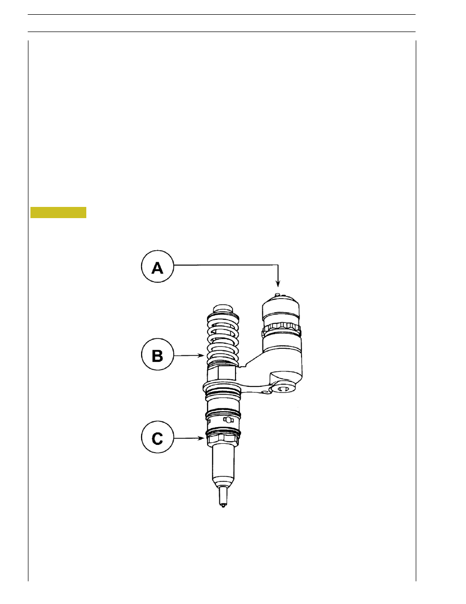
PUMP INJECTOR
It consists mainly of:
A) Solenoid valve
B) Pumping element
C) Nozzle
These three parts CANNOT be replaced individually and CANNOT be overhauled.
The pumping element, mechanically actuated at every rocker arm cycle, compresses the fuel container in the delivery chamber.
The nozzle, whose composition and operation are similar to those of traditional injectors, is opened by the fuel under pressure
and sprays it into the combustion chamber.
A solenoid valve, directly controlled by the electronic control unit, determines delivery according to the control signal.
A casing houses the lower part of the pump injector in the cylinder head.
Figure 92
000578t
36
SECTION 3 - INDUSTRIAL APPLICATION
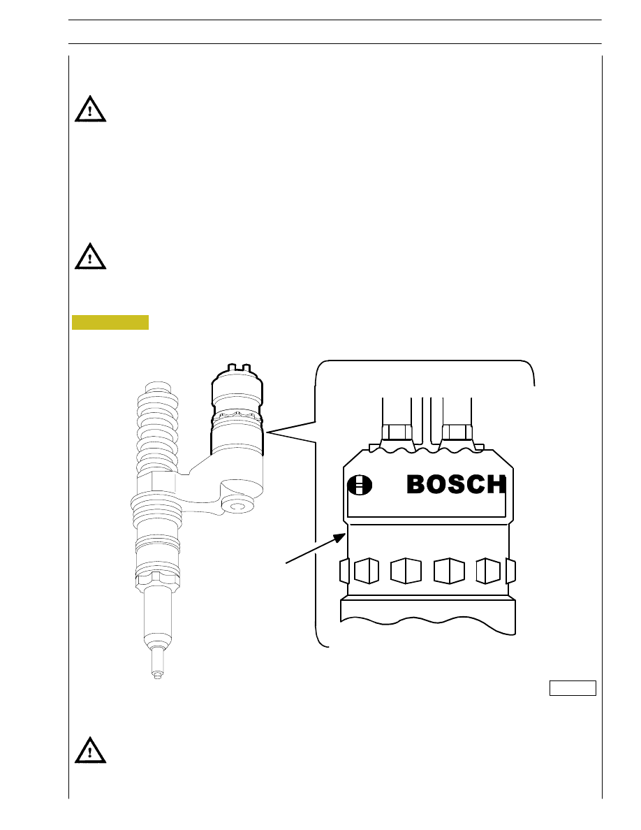
Figure 93
Pump-injector replacement
If the operation is carried out when the engine is on the vehicle, before removing the pump-injectors drain the fuel in
the cylinder head pipes by releasing the delivery and return pipe unions on the cylinder head.
In an emergency, when the Modus is not available, it is possible to replace 1 injector without the control unit recognition.
Connect to the diagnosis instrument for each replaced injector and, when required by the programme, enter the control unit
re-programming code stamped on the injector.
0 4 11 7 0 0 0 0 2
X X X X X X X X X X X
8 6 8 U S A
/
61487
When inspecting the rocker arm clearance, check also the pump-injector preload.
SECTION 3 - INDUSTRIAL APPLICATION
37
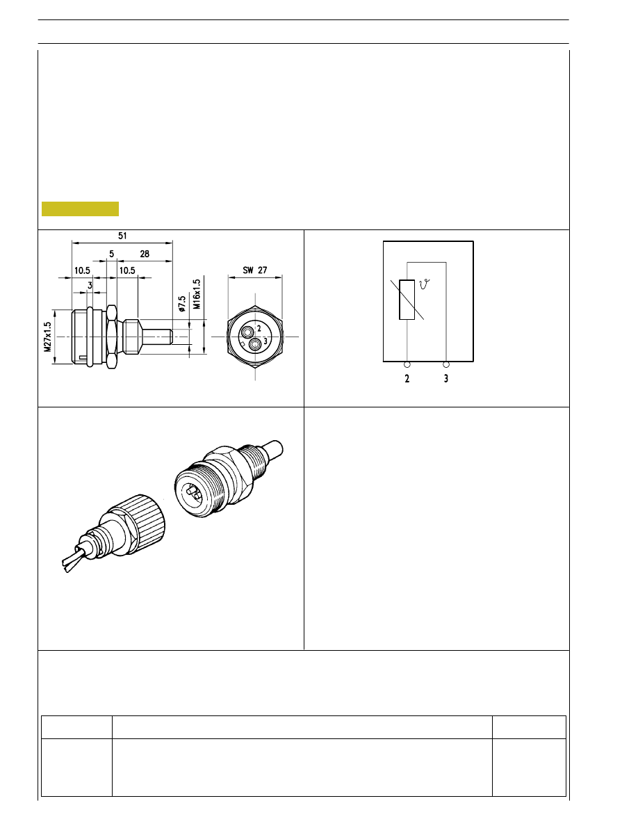
TECHNICAL VIEW
8527
000602t
WIRING DIAGRAM
PERSPECTIVE VIEW
000693t
Figure 94
38
SECTION 3 - INDUSTRIAL APPLICATION
Engine coolant temperature sensor
This N.T.C. type sensor located on the water outlet sump on the engine head left measures coolant temperature for the various
operating logics with a hot or cold engine and identifies injection enrichment requirements for a cold engine or fuel reduction
requirements for a hot engine.
It is connected to electronic center pins A5/A22.
Sensor behavior as a function of temperature:
- 10
°C
8,10
÷ 10,77 kOhm
+ 20
°C
2,28
÷ 2,72 kOhm
+ 80
°C
0,29
÷ 0,364 kOhm
At 60 to 90 _C, voltage at A5 and A22 ranges from 0.6 to 2.4V.
Connector
Function
Cable colour
2
To EDC center pin A 5
–
3
To EDC center pin A 22
–
Нет комментариевНе стесняйтесь поделиться с нами вашим ценным мнением.
Текст