Loader Bobcat 853, 853H. Manual — part 63
VALVE CLEARANCE
Adjustment
Make the valve clearance adjustment with engine
stopped and cold.
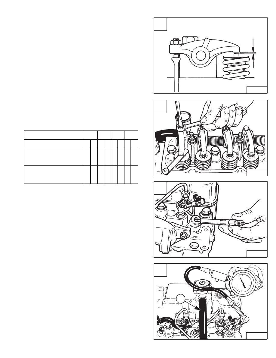
The correct clearance is 0.016 inch (0,41 mm) with the
engine cold [A].
Put the correct size feeler gauge between the rocker arm
and the valve stem. Turn the adjustment bolt until the
clearance is correct [B].
Use the following sequence to set the valve clearance:
Cylinder No.
1
2
3
4
Valve arrangement
I
E
I
E
I
E
I
E
Piston in No. 1 cylinder is
at TDC on compression
stroke
Piston in No. 4 cylinder is
at TDC on compression
stroke
• • •
•
• •
• •
Front
Rear
ENGINE COMPRESSION
Checking
The tools listed will be needed to do the following
procedure:
OEM1074 – Engine Compression Kit
MEL1268 – Compression Gauge Test Adapter
The engine must be at operating temperature.
Remove the glow plugs [C]. (See Page 7–40.)
Install the correct compression adapter into the cylinder
head.
Connect the compression gauge [D].
The engine must be turning at about 175 RPM.
The compression must be between 300–500 PSI
(2069–3448 kPa) with no more than 50 PSI (345 kPa)
difference between cylinders.
The engine has an open crankcase ventilation system.
The ventilation hose comes from the valve cover tube
(Item 1) [D] and passes down the side of the engine block.
A
B–04123
0.016 inch
(0,41 mm)
Cold
C
B–08922
D
B–08920
1
853, 853H Loader
–7–41–
Service Manual
B
B–08934

FUEL INJECTION PUMP
Description
The injection pump contains parts which have a very
close tolerance and its operation has a direct effect on the
performance of the engine.
Do not attempt to maintain or adjust unless
you are trained and have the correct
equipment.
I–2028–0289
Removal And Installation
Disconnect the throttle linkage.
Disconnect the shut–off wire [A].
Remove the valve cover.
Rotate the engine until No. 1 piston is at TDC. Both valves
at No. 1 cylinder are not moving and have clearance [B].
The TDC mark (Item 1) [C] is located on the engine pulley
v–belt groove.
There are two sets of timing marks on the engine pulley,
one at 12 o’clock and the other at the 3 o’clock position.
Use the timing marks located at the 3 o’clock position
(Inset) [C].
A
B–08976
C
P–04949
MC–01665
1
2
12 o’clock Position
12
°
14
°
TDC
3 o’clock
Position
16
°
–7–42–
853, 853H Loader
Service Manual
B
B–08935

FUEL INJECTION PUMP (Cont’d)
Removal And Installation (Cont’d)
Use the parting line (off–set) (Item 2) [A] or (Item 1) [B]
of the timing case cover to make alignment of the TDC
mark.
Early S/N Loader:
Disregard the pointer (Item 1) [C] in the belt shield for
timing reference.
Align the mark on the injection pump gear with the pointer
in the window [D].
A
P–04949
1
C
1
D
B–08939
853, 853H Loader
–7–43–
Service Manual
B
P–04952
1
FUEL INJECTION PUMP (Cont’d)
Removal And Installation (Cont’d)
Do not bend the high pressure fuel injection
tubes when removing or installing them.
I–2029–0289
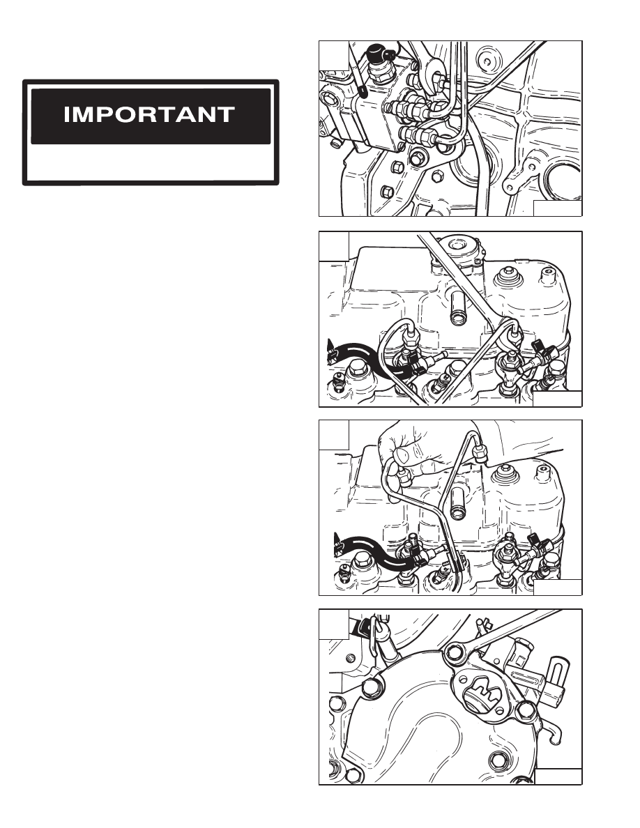
Disconnect the high pressure fuel lines at the injection
pump [A].
Disconnect the fuel lines at the injectors [B].
Installation: Tighten the fittings on the high pressure fuel
lines to 14–29 ft.–lbs. (19–39 Nm) torque.
Remove the high pressure fuel lines from the engine [C].
Align the mark in the window before removing the
injection pump [A].
Remove the bolts at the front of the timing case cover [D].
Installation: Tighten bolts & nuts to 10–17 ft.–lbs. (14–23
Nm) torque.
A
B–08975
C
B–08915
D
B–08938
–7–44–
853, 853H Loader
Service Manual
B
B–08917
Нет комментариевНе стесняйтесь поделиться с нами вашим ценным мнением.
Текст