Loader Bobcat 853, 853H. Manual — part 64

FUEL INJECTION PUMP (Cont’d)
Removal And Installation (Cont’d)
Remove the fuel injection pump [A].
Installation: After the injection pump is installed, the air
must be removed from the fuel system. (See Page 1–1.)
Also the injection pump timing must be set. (See Page
7–46.)
A
B–08913
853, 853H Loader
–7–45–
Service Manual

FUEL INJECTION PUMP (Cont’d)
Timing The Injection Pump
The tools listed will be needed to do the following
procedure:
MEL1201 – Timing Tool
Remove the valve cover.
Rotate the engine until No. 1 piston is at TDC. Both valves
at No. 1 cylinder are not moving and have clearance [A].
The TDC mark (Item 1) [B] is located on the engine pulley
v–belt groove.
There are two sets of timing marks on the engine pulley
one at 12 o’clock and the other at the 3 o’clock position.
Use the timing mark located at the 3 o’clock position
(Inset) [B].
Use the parting line (off–set) (Item 2) [B] or (Item 1) [C]
of the timing case cover to make alignment of the TDC
mark.
Disregard the pointer (Item 2) [C] in the belt shield for
timing reference.
Remove the plug at the rear of the injection pump [D].
A
B–08935
2
1
C
D
B–08921
–7–46–
853, 853H Loader
Service Manual
B
P–04949
1
2
MC–01665
12 o’clock Position
12
°
14
°
TDC
3 o’clock
Position
16
°
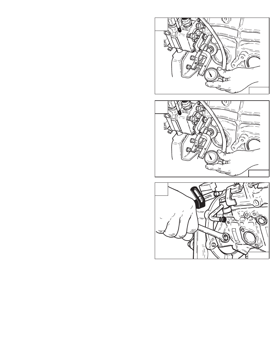
FUEL INJECTION PUMP (Cont’d)
Timing The Injection Pump (Cont’d)
Install the timing tool and dial indicator [A].
Rotate the engine counterclockwise so the front pulley
mark goes 30
°
to 40
°
before TDC.
Set the dial indicator to zero [B].
Rotate the engine back to 17
°
BTDC mark on the front
pulley.
The dial indicator must read approximately 0.020 inch
(0,50 mm) [B].
If not, loosen the bolts at the injection pump flange [C].
Move the injection pump to obtain the 0.020–0.022 inch
(0,51–0,59 mm) reading at the dial indicator with the front
pulley marks at the 17
°
BTDC.
Repeat the procedure until the timing is correct.
A
B–08977
C
B–08910
853, 853H Loader
–7–47–
Service Manual
B
B–08977

FUEL INJECTOR NOZZLES
Removal And Installation
Diesel fuel or hydraulic fluid under pressure
can penetrate skin or eyes causing serious
injury. Fluid leaks under pressure may not be
visible. Use a piece of cardboard or wood to
find leaks. Do not use your bare hand. Wear
safety goggles. If fluid enters skin or eyes, get
immediate medical attention.
W–2074–1285
Some problems caused by faulty injector nozzles:
The engine is hard to start or will not start.
Rough engine operation and idle.
The engine will not have full power.
The engine exhaust smoke is black, white or blue.
Do not bend the high pressure fuel injection
tubes when removing or installing them.
I–2029–0289
Disconnect the high pressure fuel lines at the fuel
injection pump [A].
Installation: Tighten the fittings on the high pressure fuel
lines to 14–29 ft.–lbs. (19–39 Nm) torque.
Disconnect the fuel lines at the fuel injectors [B].
Remove the high pressure fuel lines from the engine [C].
Remove the low pressure hoses from the fuel injector
nozzles [D].
A
B–08975
C
B–08915
D
B–08918
–7–48–
853, 853H Loader
Service Manual
B
B–08917
Нет комментариевНе стесняйтесь поделиться с нами вашим ценным мнением.
Текст