Loader Bobcat 853, 853H. Manual — part 24
HYDROSTATIC
SYSTEM
853, 853H Loader
–3–1–
Service Manual
HYDROSTATIC SYSTEM
COLD OIL BY–PASS VALVE
Removal And Installation
3–21
. . . . . . . . . . . . . . . . . . . . . . . . . . . . . . . . . . . . . . .
DRIVE BELT
Replacing The Drive Belt
3–27
. . . . . . . . . . . . . . . . . . . . . . . . . . . . . . . . . . . . . . .
DRIVE BELT SHIELD
Removal And Installation
3–26
. . . . . . . . . . . . . . . . . . . . . . . . . . . . . . . . . . . . . . .
FIXED TENSIONER PULLEY
Adjusting The Drive Belt
3–41
. . . . . . . . . . . . . . . . . . . . . . . . . . . . . . . . . . . . . . .
Assembly
3–36
. . . . . . . . . . . . . . . . . . . . . . . . . . . . . . . . . . . . . . . . . . . . . . . . . . . .
Checking Pulley End Play
3–40
. . . . . . . . . . . . . . . . . . . . . . . . . . . . . . . . . . . . . .
Disassembly
3–34
. . . . . . . . . . . . . . . . . . . . . . . . . . . . . . . . . . . . . . . . . . . . . . . . . .
Removal And Installation
3–33
. . . . . . . . . . . . . . . . . . . . . . . . . . . . . . . . . . . . . . .
FRONT PANEL
Removal And Installation
3–5
. . . . . . . . . . . . . . . . . . . . . . . . . . . . . . . . . . . . . . .
HYDROSTATIC CHARGE OIL FILTER
Removal And Installation
3–19
. . . . . . . . . . . . . . . . . . . . . . . . . . . . . . . . . . . . . . .
HYDROSTATIC MOTOR
Removal And Installation
3–17
. . . . . . . . . . . . . . . . . . . . . . . . . . . . . . . . . . . . . . .
HYDROSTATIC PUMP
Removal And Installation
3–23
. . . . . . . . . . . . . . . . . . . . . . . . . . . . . . . . . . . . . . .
Replenishing/High Pressure Relief Valve
3–25
. . . . . . . . . . . . . . . . . . . . . . . . .
HYDROSTATIC SYSTEM INFORMATION
Replenishing Valve Function
3–4
. . . . . . . . . . . . . . . . . . . . . . . . . . . . . . . . . . . .
Tow Valves
3–4
. . . . . . . . . . . . . . . . . . . . . . . . . . . . . . . . . . . . . . . . . . . . . . . . . . .
OIL COOLER
Removal And Installation
3–42
. . . . . . . . . . . . . . . . . . . . . . . . . . . . . . . . . . . . . . .
SPRING LOADED TENSIONER PULLEY
Adjusting The Drive Belt
3–32
. . . . . . . . . . . . . . . . . . . . . . . . . . . . . . . . . . . . . . .
Assembly
3–30
. . . . . . . . . . . . . . . . . . . . . . . . . . . . . . . . . . . . . . . . . . . . . . . . . . . .
Disassembly
3–29
. . . . . . . . . . . . . . . . . . . . . . . . . . . . . . . . . . . . . . . . . . . . . . . . . .
Parts Idenification
3–28
. . . . . . . . . . . . . . . . . . . . . . . . . . . . . . . . . . . . . . . . . . . . .
STEERING LEVERS
Adjusting Lever Freeplay
3–10
. . . . . . . . . . . . . . . . . . . . . . . . . . . . . . . . . . . . . . .
Adjusting The Steering Neutral Setting
3–13
. . . . . . . . . . . . . . . . . . . . . . . . . . .
Adjusting The Wheel RPM Forward Compared To Reverse Travel
3–11
. . .
Adjusting The Wheel RPM Left Compared To Right Side
3–14
. . . . . . . . . . .
Disassembly And Assembly
3–7
. . . . . . . . . . . . . . . . . . . . . . . . . . . . . . . . . . . .
Neutral Pre–Adjustment Checks
3–9
. . . . . . . . . . . . . . . . . . . . . . . . . . . . . . . .
Hydrostatic Pump Neutral Adjustment
3–15
. . . . . . . . . . . . . . . . . . . . . . . . . . . .
TROUBLESHOOTING
Chart
3–3
. . . . . . . . . . . . . . . . . . . . . . . . . . . . . . . . . . . . . . . . . . . . . . . . . . . . . . . .
Page
Number

TROUBLESHOOTING
Chart
The following troubleshooting chart is provided for
assistance in locating and correcting problems which are
most common. Many of the recommended procedures
must be done by authorized Bobcat Service Personnel
only.
W–2004–1285
Check for correct function after adjustments,
repairs or service. Failure to make correct
repairs or adjustments can cause injury or
death.
No drive on one side, in one direction.
1, 2
No drive on one side in both directions.
2, 3, 4, 5
The loader does not move in a straight line.
2, 3, 5, 6, 7
The hydrostatic system is overheating.
8, 9, 10, 11
Service code HP 2 appears (Warnings, low charge pressure) or the
warning light comes ON (853 Base).
8, 11, 12, 13, 14
1.
The hydrostatic pump replenishing valves not seating.
2.
The steering linkage needs adjustment.
3.
The hydrostatic pump has damage.
4.
The final drive chains are broken.
5.
The hydrostatic motor has damage.
6.
The tires do not have the correct tire pressure.
7.
The tires are not the same size.
8.
The hydrostatic fluid is not at the correct level.
9.
The oil cooler has a restriction.
10.
The temperature sending switch is not operating correctly.
11.
The loader is not being operated at the correct RPM.
12.
The sender is defective.
13.
Pump is defective or worn hydrostatics.
14.
Hydraulic filter is plugged.
PROBLEM
CAUSE
KEY TO CORRECT THE CAUSE
853, 853H Loader
–3–3–
Service Manual
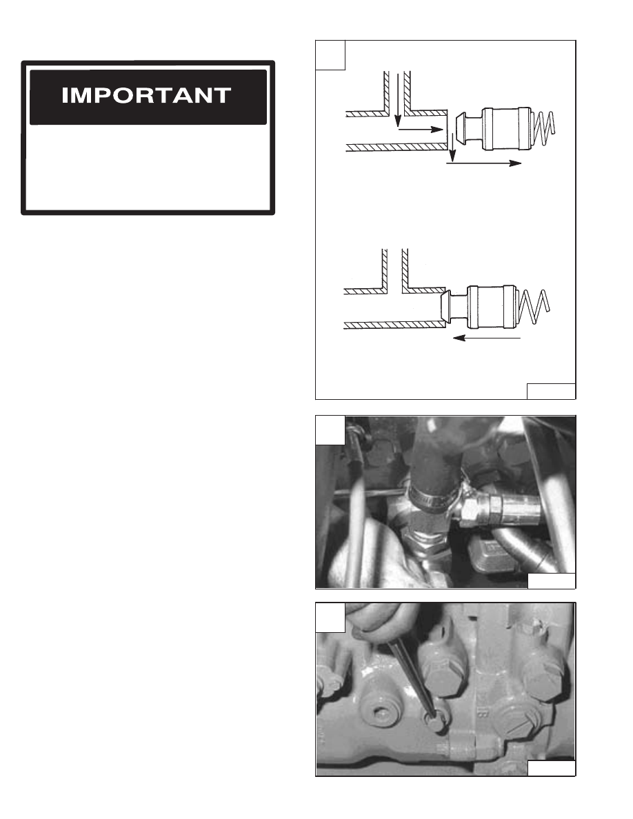
Replenishing Valve Function
The functions of the replenishing valves are:
HYDROSTATIC SYSTEM INFORMATION
When making repairs on hydrostatic and
hydraulic systems, clean the work area before
disassembly and keep all parts clean. Always
use caps and plugs on hoses, tubelines and
ports to keep dirt out. Dirt can quickly damage
the system.
I–2003–0284
1. To give replacement fluid to the low pressure side of
the hydrostatic circuit. Replacement fluid is needed
because of normal internal leakage and the
controlled flow to the oil cooler for cooling; Function
1 [A].
2. To keep high pressure fluid out of the low pressure
side of the hydrostatic circuitry; Function 2 [A].
Tow Valves
The loader can be moved for a short distance when the
tow valves are open.
Turn the two valves open one half turn before moving the
loader [B] [C].
NOTE: After moving the loader with the tow valves
open, make sure the two valves are
completely closed and tight because they
have a direct effect on the operation of the
loader drive system.
A
B–02804
CHARGE OIL
Valve Moves for Charge
Oil Replacement
Valve Stays on Seat to
Hold High Pressure for Drive
FUNCTION 1
FUNCTION 2
B
CD–11194
C
CD–11195
–3–4–
853, 853H Loader
Service Manual

FRONT PANEL
Removal And Installation
Put jackstands under the front axles and rear
corners of the frame before running the engine
for service. Failure to use jackstands can allow
the machine to fall or move and cause injury or
death.
W–2017–0286
Raise the operator cab. (See Page 1–1.)
Remove the mounting bolts (Item 1) [A] from the throttle
lever.
Disconnect the linkage rod (Item 1) [B] from the throttle
lever.
Disconnect the wire harness connectors (Item 1) [C]from
the steering lever wire harness.
NOTE: The 853 without front auxiliary hydraulics
does not have electric control handle.
Remove the right side steering shock (Item 2) [D].
NOTE: Early S/N loaders do not have steering panel
braces (Item 3) [C]. The right side steering
shock is mounted inside the steering panel.
Remove the steering panel brace bolts (Item 1) [D].
NOTE: Bolts have a nut on rear side holding panel
brace.
Never work on a machine with the lift arms up
unless the lift arms are secured by an approved
lift arm support device. Failure to use an
approved lift arm support device can allow the
lift arms or attachment to fall and cause injury
or death.
W–2059–0598
A
P–09926
1
C
P–04737
3
2
1
D
P–09329
1
1
853, 853H Loader
–3–5–
Service Manual
B
P–09927
1
Нет комментариевНе стесняйтесь поделиться с нами вашим ценным мнением.
Текст