Loader Bobcat 853, 853H. Manual — part 23

FRONT AUXILIARY CONTROL VALVE (Apitech)
Removal And Installation
(S/N 508411001 – 15215)
(S/N 509711001 & Above)
(S/N 510375001 & Above)
(S/N 510125001 – 16791) (W/Front Aux. Opt.)
(S/N 510250001 – 50691)
(S/N 512811001 & Above) (Ww/Apitech)
Always clean up spilled fuel or oil. Keep heat,
flames, sparks or lighted tobacco away from
fuel and oil. Failure to use care around
combustibles can cause explosion or fire
which can result in injury or death.
W–2103–1285
Disconnect the outlet tubeline which returns to the
hydraulic filter [B].
Disconnect the two auxiliary tubelines [B].
Disconnect the solenoid connector [C].
Remove the two mounting bolts and remove the auxiliary
control valve [D].
Installation: Tighten the mounting bolts to 64–70 ft.–lbs.
(88–95 Nm) torque.
Never work on a machine with the lift arms up
unless the lift arms are secured by an approved
lift arm support device. Failure to use an
approved lift arm support device can allow the
lift arms or attachment to fall and cause injury
or death.
W–2059–0598
A
CD–10962
C
N–10964
D
CD–10965
853, 853H BICS Loader
–2–41–
Service Manual
B
CD–10963
CONTROL PEDALS
Removal And Installation
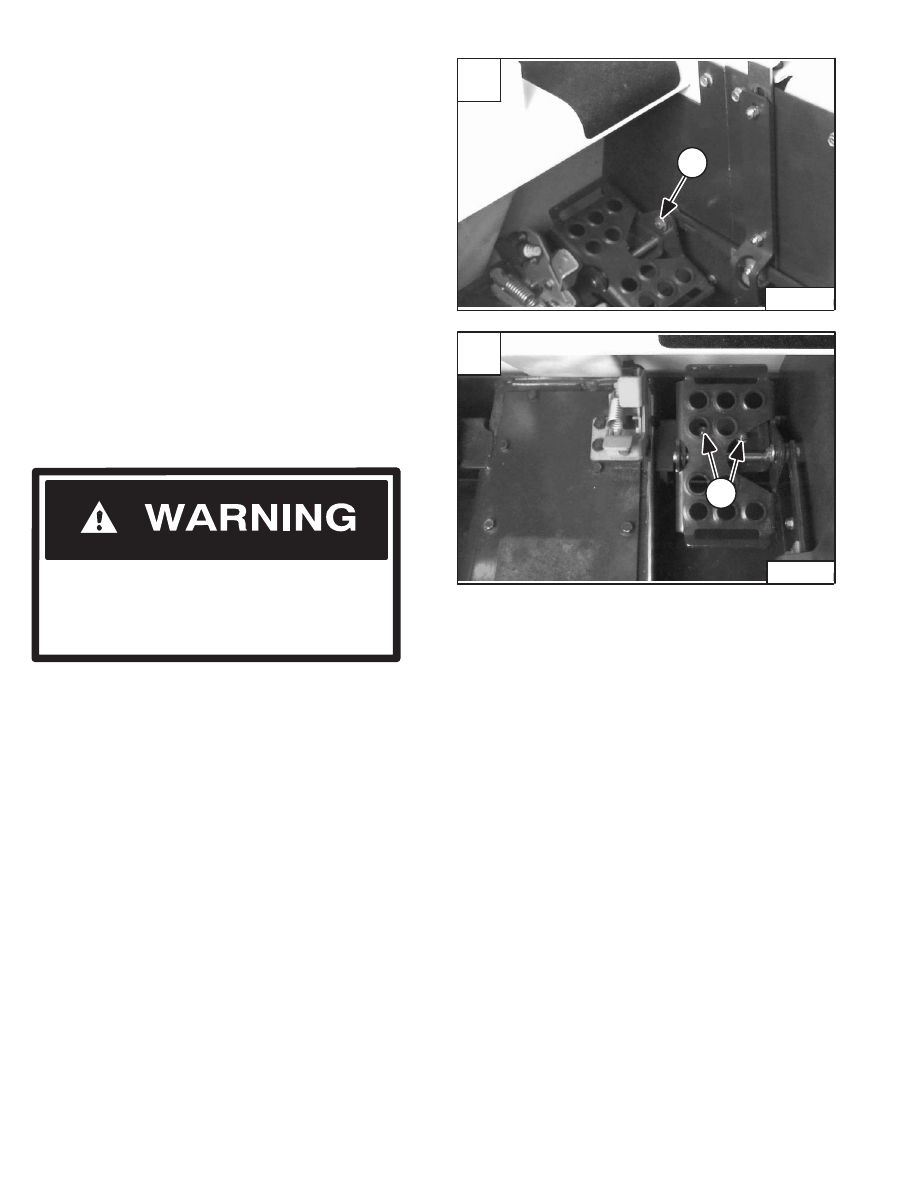
Remove the bolt and nut (Item 1) [A] from the pedal
linkage.
Installation: Tighten the bolt and nut to 21–25 ft.–lbs.
(28–34 Nm) torque.
Check the rubber bushing in the pedal for wear and
replace as needed.
Remove the two mounting bolts (Item 1) [B].
Remove the pedal assembly from the loader.
Pedal Adjustment
After installing the pedal, adjust the pedal so that there is
clearance under the rear of the pedal and the valve spool
must travel full stroke without hitting the floor panel.
W–2104–1285
Adjust locking tabs on pedal control linkage so
that lift and tilt control pedals are locked in
neutral when the seat bar is up.
AVOID INJURY OR DEATH
NOTE: See Page 2–44 for correct procedure to
adjust the pedal interlock linkage.
A
P–04771
1
–2–42–
853, 853H BICS Loader
Service Manual
B
P–04770
1
PEDAL INTERLOCK LINKAGE
Removal And Installation
Raise the lift arms and install an approved lift arm support
device. (See Page 1–1.)
Raise the operator cab. (See Page 1–1.)
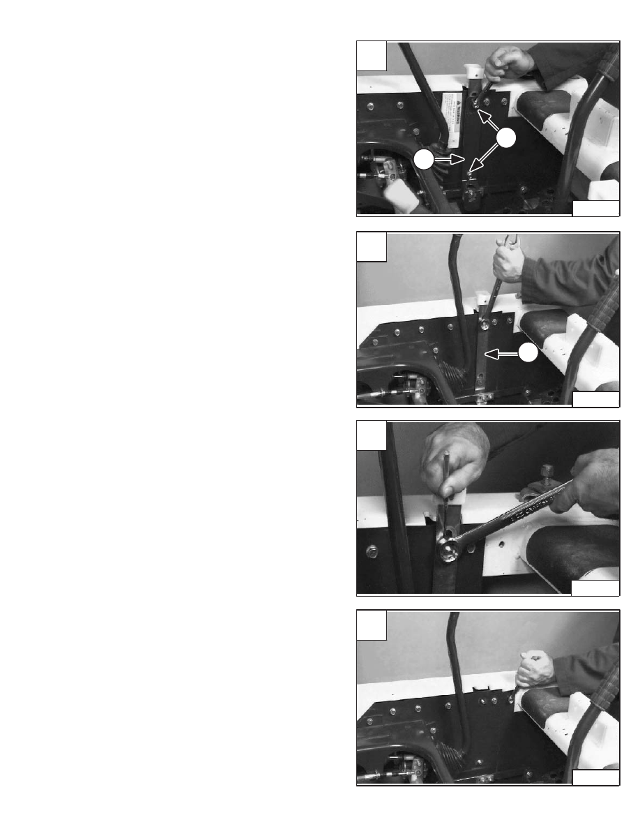
Remove the interlock shield mounting nuts (Item 1) [A].
Installation: Tighten the shield mounting nuts to 25–28
ft.–lbs. (34–38 Nm) torque.
Remove the interlock shield (Item 2) [A].
Remove the interlock mounting nuts and plastic washers
from behind the nuts [B].
Remove the interlock (Item 1) [B] and plastic washers
from behind the interlock.
Installation: Hold the inside plastic washer up with an
O–ring pick or a small screwdriver so the plastic washer
does not become wedged between the side panel and the
interlock nut [C].
Installation: Tighten the interlock mounting nuts to
84–95 in.–lbs. (9,5–10,8 Nm) torque.
To install new interlock mounting bolts, remove the top
bolt from the front panel and loosen the two bolts at the
bottom of the panel [D].
A
P–01216
2
1
C
P–01219
D
P–01213
853, 853H BICS Loader
–2–43–
Service Manual
B
P–01210
1

PEDAL INTERLOCK LINKAGE (Cont’d)
Removal And Installation (Cont’d)
Remove the panel from the loader frame [A].
Install the mounting bolts (Item 1) [B] through the back of
the panel as shown.
Pedal Interlock Linkage Adjustment
Check the pedal interlock linkage so it is free and locks
both pedals.
Check that the tab (Item 1) [C] on the linkage, slides into
the slot on the interlock and holds the pedal in locked
position.
If not, loosen the bolts and adjust the tab for correct
engagement.
Tighten the bolts to 25–28 ft.–lbs. (34–38 Nm) torque.
W–2104–1285
Adjust locking tabs on pedal control linkage so
that lift and tilt control pedals are locked in
neutral when the seat bar is up.
AVOID INJURY OR DEATH
The locking tab should fit into the slot of the interlock as
shown in figure [D], when adjusted correctly.
A
P–01215
C
P–01214
1
D
P–04051
–2–44–
853, 853H BICS Loader
Service Manual
B
P–01212
1
Нет комментариевНе стесняйтесь поделиться с нами вашим ценным мнением.
Текст