Loader Bobcat 853, 853H. Manual — part 73
OIL PAN
Removal
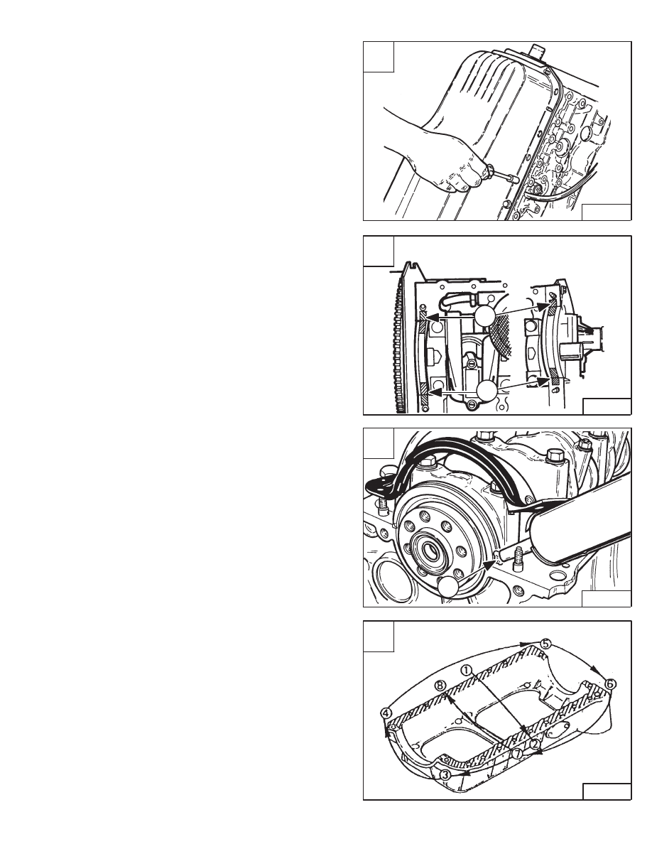
Remove the oil drain plug and remove the oil.
Remove the fastening bolts and nuts from the oil pan [A].
Installation
Clean the surface on the oil pan and engine block.
Put Three Bond (TB–1207B) at the front and rear main
bearing caps (Item 1) [B] & [C].
Put liquid gasket on the oil pan surface area of the engine
block.
Install the oil pan. Install and tighten the bolts in the
sequence shown [D].
Tighten the bolts and nuts to 13–18 ft.–lbs. (19–26 Nm)
torque.
A
B–08953
C
B–08911
1
D
B–12200
853, 853H Loader
–7–81–
Service Manual
B
B–08418
1
1

OIL PUMP
Removal And Installation
Remove the oil pan. (See Page 7–81.)
Remove the bolts at the oil pump [A].
Installation: Tighten the bolts to 10–17 ft.–lbs. (14–23
Nm) torque.
Remove the oil pump assembly from the engine block [B].
Checking
Disassemble the oil pump as illustrated [C].
A
B–08912
C
B–08420
1
4
3
2
1.
Oil Pipe
2.
Strainer
3.
Pump Cover
4.
Vane
–7–82–
853, 853H Loader
Service Manual
B
B–08982
OIL PUMP (Cont’d)
Checking (Cont’d)
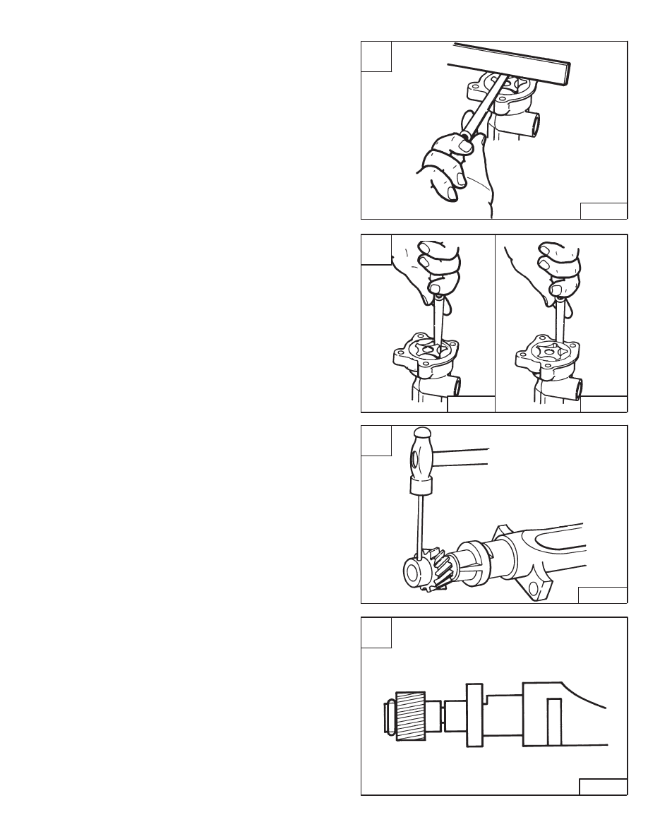
Check the clearance between vane and body [A].
Standard – 0.0008–0.0028 inch (0,02–0,07 mm)
Limit – 0.0059 inch (0,15 mm)
Check the clearance between the rotor and vane [B].
Standard – 0.0055 inch (0,14 mm) or less.
Check the clearance between the vane and pump body
[B].
Standard – 0.0079–0.0105 inch (0,20–0,27 mm)
Check clearance between rotor shaft and pump body.
Standard – 0.0016 inch (0,04 mm)
Limit – 0.0079 inch (0,2 mm)
Gear Replacement
File off one end of the roll pin at the gear. Use a punch and
hammer and remove the pin [C].
NOTE: It may be necessary to drill a hole in one side
of the gear for service as it does not have a
hole on both sides [D].
Installation: Install the gear and new pin. Peen the end
of the pin after installation.
A
B–08421
C
B–08424
D
B–08425
853, 853H Loader
–7–83–
Service Manual
B
B–08423
B–08422
OIL PUMP (Cont’d)
Rotor Replacement
Remove the pin at the rotor using a punch and hammer
[A].
Installation: When installing the new pin in the rotor,
make sure to check the end of the pin that it does not
project from the end of the rotor [A].
After the oil pump is assembled, put oil into the pump and
turn the shaft to prime the pump.
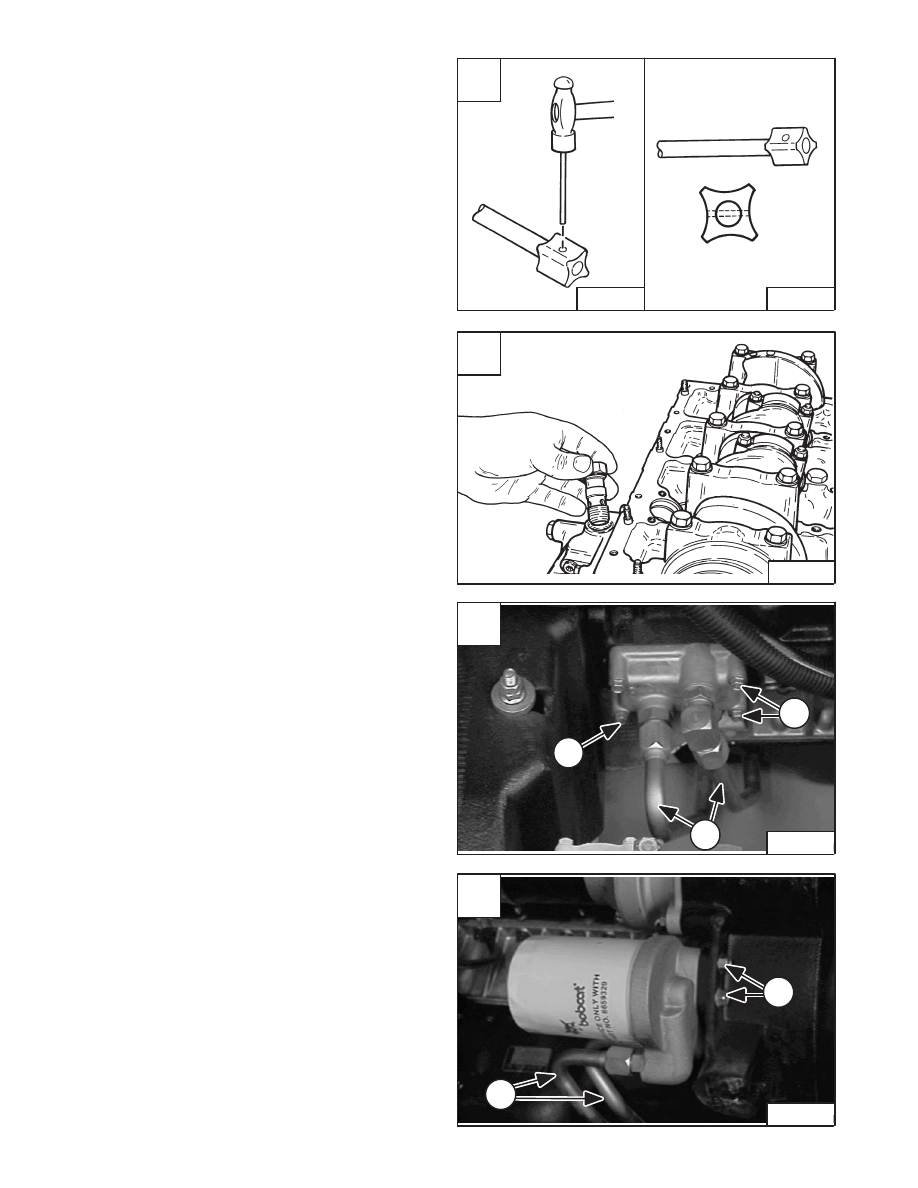
Oil Pump Relief Valve
Remove the relief valve from the oil filter housing [B].
Check the relief valve and clean. Replace as needed.
Oil Filter Housing And Block
To remove the oil filter block & housing, disconnect the
tubelines (Item 1) [C] & [D].
remove the four mounting bolts (Item 2) [C] at the block.
Remove the two mounting bolts (Item 2) [D] at the oil filter
housing.
A
B–08427
B–08426
C
P–04943
1
2
2
D
P–04953
2
1
–7–84–
853, 853H Loader
Service Manual
B
B–08949
Нет комментариевНе стесняйтесь поделиться с нами вашим ценным мнением.
Текст