Loader Bobcat 853, 853H. Manual — part 72

TIMING GEARCASE
Removal And Installation
Remove the timing gearcase cover. (See Page 7–71.)
Remove the idler gear. (See Page 7–73.)
Remove the fuel injection pump. (See Page 7–42.)
Remove the fuel injection pump idler gear. (See Page
7–75.)
Remove the camshaft gear. (See Page 7–76.)
Remove the water pump. (See Page 7–85.)
Remove the oil pan. (See Page 7–81.)
Remove the bolts at the timing case [A].
Installation: Tighten the bolts to 11–17 ft.–lbs. (15–23
Nm) torque.
Remove the timing case [B].
Installation: After the timing case cover is installed with
the new gasket, cut the excess gasket at the engine block
[C].
A
B–08925
C
B–08952
853, 853H Loader
–7–77–
Service Manual
B
B–08937
CAMSHAFT
Removal And Installation
Remove the rocker arm cover, rocker arm assembly and
the push rods. (See Page 7–56.)
Remove the timing gearcase cover. (See Page 7–71.)
Remove the camshaft gear. (See Page 7–76.)
Remove the oil pan and oil pump. (See Pages 7–81 &
7–82.)
Remove the camshaft from the engine.
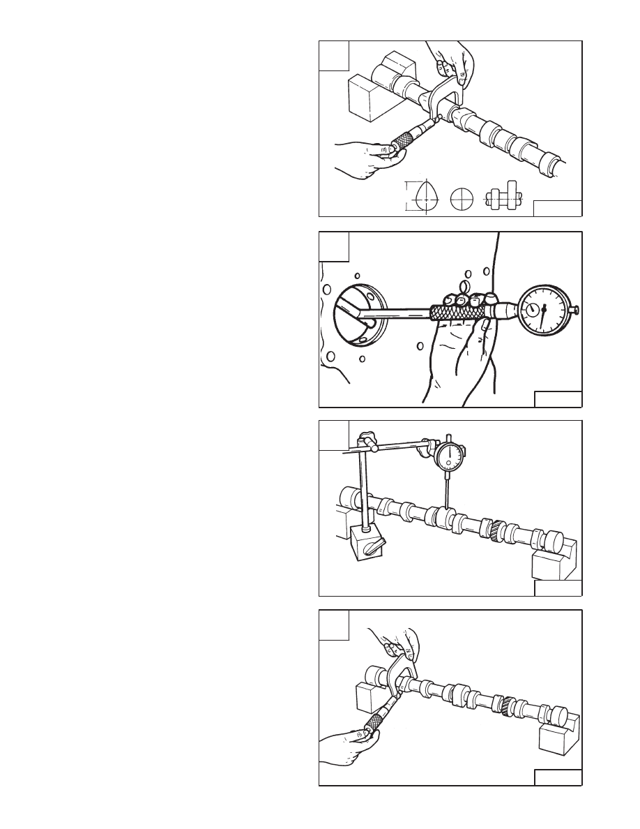
Checking
Check the camshaft journals [A].
Standard – 1.9662–1.9675 inch (49,945–49,975 mm)
Limit – 1.9528 inch (49,60 mm)
Check the bearing inside diameter [B].
Standard – 1.9685–1.9697 inch (50,0–50,03 mm)
Clearance between camshaft journal and bearing:
Standard – 0.002 inch. (0,05 mm)
Limit – 0.0047 inch (0,12 mm)
Check camshaft run–out [C].
Limit – 0.0039 inch (0,10 mm)
Check cam lobe height [D].
Standard – 1.654 inch (42,02 mm)
Limit – 1.640 inch (41,65 mm)
A
B–08217
C
B–08221
D
B–08222
–7–78–
853, 853H Loader
Service Manual
B
B–08218

CAMSHAFT (Cont’d)
Camshaft Bearings
The tools listed will be needed to do the following
procedure:
MEL1260 – Camshaft Bearing Remover/Installer
Use the correct tool to remove the bearings [A].
When installing the new bearings, make sure to align the
oil hole in the bearing with the hole in the engine block
(Item 1) [B].
Tappets
Remove the tappets from the engine block. Mark the
cylinder number on each tappet after removal [C].
Inspect the tappets for wear, damage or abnormal
conditions [D].
A
B–08219
C
B–08190
D
B–08210
Pitted
Crack
Normal Contact
Irregular Contact
853, 853H Loader
–7–79–
Service Manual
B
B–08220
1

CAMSHAFT (Cont’d)
Tappets (Cont’d)
Check the diameter of the tappets [A].
Standard – 0.511–0.5114 inch (12,98–12,99 mm)
Limit – 0.510 inch (12,95 mm)
Clearance between tappet and engine block bore as
listed [B].
Standard – 0.0012 inch (0,03 mm)
Limit – 0.0039 inch (0,09 mm)
Tappet Installation
Lubricate the tappets before installation.
Lubricate the camshaft bearings and journals. Install the
camshaft, carefully not to damage the bearings.
Install the camshaft gear. (See Page 7–76.)
Check the camshaft end play using a feeler gauge [C].
Standard – 0.0002–0.0045 inch (0,05–0,114 mm)
Limit – 0.0079 inch (0,20 mm)
After the rocker arm assembly is installed, make sure to
set the valve clearance. (See Page 7–41.)
A
B–08211
C
B–08216
–7–80–
853, 853H Loader
Service Manual
B
B–08212
Нет комментариевНе стесняйтесь поделиться с нами вашим ценным мнением.
Текст