Loader Bobcat 853, 853H. Manual — part 78
SPECIFICATIONS
853, 853H Loader
–9–1–
Service Manual
SPECIFICATIONS
DECIMAL & MILLIMETER EQUIVALENTS
Chart
9–17
. . . . . . . . . . . . . . . . . . . . . . . . . . . . . . . . . . . . . . . . . . . . . . . . . . . . . . . .
ENGINE SPECIFICATIONS
Camshaft
9–6
. . . . . . . . . . . . . . . . . . . . . . . . . . . . . . . . . . . . . . . . . . . . . . . . . . . .
Connecting Rod & Bearing
9–6
. . . . . . . . . . . . . . . . . . . . . . . . . . . . . . . . . . . . .
Crankshaft
9–7
. . . . . . . . . . . . . . . . . . . . . . . . . . . . . . . . . . . . . . . . . . . . . . . . . . .
Cylinder Head
9–5
. . . . . . . . . . . . . . . . . . . . . . . . . . . . . . . . . . . . . . . . . . . . . . . .
Cylinder Liners
9–6
. . . . . . . . . . . . . . . . . . . . . . . . . . . . . . . . . . . . . . . . . . . . . . . .
Fuel System
9–7
. . . . . . . . . . . . . . . . . . . . . . . . . . . . . . . . . . . . . . . . . . . . . . . . . .
Idler Gear
9–7
. . . . . . . . . . . . . . . . . . . . . . . . . . . . . . . . . . . . . . . . . . . . . . . . . . . .
Oil Pump
9–7
. . . . . . . . . . . . . . . . . . . . . . . . . . . . . . . . . . . . . . . . . . . . . . . . . . . . .
Pistons, Pins & Rings
9–6
. . . . . . . . . . . . . . . . . . . . . . . . . . . . . . . . . . . . . . . . . .
Rocker Arm
9–5
. . . . . . . . . . . . . . . . . . . . . . . . . . . . . . . . . . . . . . . . . . . . . . . . . .
Tappets
9–5
. . . . . . . . . . . . . . . . . . . . . . . . . . . . . . . . . . . . . . . . . . . . . . . . . . . . . .
Valve Springs
9–5
. . . . . . . . . . . . . . . . . . . . . . . . . . . . . . . . . . . . . . . . . . . . . . . . .
Valve, Valve Guide & Seat Insert
9–5
. . . . . . . . . . . . . . . . . . . . . . . . . . . . . . . .
HYDRAULIC CONNECTION SPECIFICATIONS
Flare Fitting
9–12
. . . . . . . . . . . . . . . . . . . . . . . . . . . . . . . . . . . . . . . . . . . . . . . . . .
O–ring Face Seal Connection
9–12
. . . . . . . . . . . . . . . . . . . . . . . . . . . . . . . . . . .
O–ring Flare Fitting
9–13
. . . . . . . . . . . . . . . . . . . . . . . . . . . . . . . . . . . . . . . . . . . .
Port Seal Fitting
9–15
. . . . . . . . . . . . . . . . . . . . . . . . . . . . . . . . . . . . . . . . . . . . . . .
Straight Thread O–ring Fitting
9–12
. . . . . . . . . . . . . . . . . . . . . . . . . . . . . . . . . .
Tubelines And Hoses
9–12
. . . . . . . . . . . . . . . . . . . . . . . . . . . . . . . . . . . . . . . . . .
HYDRAULIC/HYDROSTATIC FLUID SPECIFICATIONS
Specifications
9–16
. . . . . . . . . . . . . . . . . . . . . . . . . . . . . . . . . . . . . . . . . . . . . . . . .
LOADER SPECIFICATIONS
Capacities
9–4
. . . . . . . . . . . . . . . . . . . . . . . . . . . . . . . . . . . . . . . . . . . . . . . . . . . .
Controls
9–3
. . . . . . . . . . . . . . . . . . . . . . . . . . . . . . . . . . . . . . . . . . . . . . . . . . . . . .
Drive System
9–4
. . . . . . . . . . . . . . . . . . . . . . . . . . . . . . . . . . . . . . . . . . . . . . . . .
Electrical
9–4
. . . . . . . . . . . . . . . . . . . . . . . . . . . . . . . . . . . . . . . . . . . . . . . . . . . . .
Engine
9–3
. . . . . . . . . . . . . . . . . . . . . . . . . . . . . . . . . . . . . . . . . . . . . . . . . . . . . . .
Hydraulic System
9–4
. . . . . . . . . . . . . . . . . . . . . . . . . . . . . . . . . . . . . . . . . . . . .
Loader Dimensions
9–3
. . . . . . . . . . . . . . . . . . . . . . . . . . . . . . . . . . . . . . . . . . . .
Operation & Performance
9–3
. . . . . . . . . . . . . . . . . . . . . . . . . . . . . . . . . . . . . .
Tires
9–4
. . . . . . . . . . . . . . . . . . . . . . . . . . . . . . . . . . . . . . . . . . . . . . . . . . . . . . . . .
TORQUE SPECIFICATIONS FOR BOLTS
Torque For General SAE Bolts
9–10
. . . . . . . . . . . . . . . . . . . . . . . . . . . . . . . . . .
Torque For General Metric Bolts
9–11
. . . . . . . . . . . . . . . . . . . . . . . . . . . . . . . .
TORQUE SPECIFICATIONS FOR LOADER
Specifications
9–9
. . . . . . . . . . . . . . . . . . . . . . . . . . . . . . . . . . . . . . . . . . . . . . . . .
U.S. TO METRIC CONVERSION
Chart
9–17
. . . . . . . . . . . . . . . . . . . . . . . . . . . . . . . . . . . . . . . . . . . . . . . . . . . . . . . .
Page
Number

–9–2–
853, 853H Loader
Service Manual
Operating Weight
6497 lbs. (2950 kg)
. . . . . . . . . . . . . . . . . . .
Rated Operating Capcity
1700 lbs. (772 kg)
. . . . . . . . . . . . .
Tipping Load
3420 lbs. (1533 kg)
. . . . . . . . . . . . . . . . . . . . . . .
Travel Speed
Infinitely variable 0–6.3 MPH (10,1 km/hr.)
. . . . . . . . . . . . . . . . . . . . . . . .
Controls
Vehicle
Direction & speed controlled by two hand levers.
. . . . . . . . . . . . . . . . . . . . . . . . . . . .
Loader Function
Lift, tilt functions controlled by separate foot pedals. Auxiliary functions
. . . . . . . . . . . . . . . . . . . .
controlled by electrical push buttons on steering levers
Engine
Hand lever throttle; key–type starter switch.
. . . . . . . . . . . . . . . . . . . . . . . . . . . . .
Main Drive
Hydrostatic
. . . . . . . . . . . . . . . . . . . . . . . . .
Parking Brake
Mechanical disc, foot operated pedal
. . . . . . . . . . . . . . . . . . . . . .
Engine
Make
Isuzu
. . . . . . . . . . . . . . . . . . . . . . . . . . . . . .
Model
4JB1 PK–03
. . . . . . . . . . . . . . . . . . . . . . . . . . . . .
Fuel
Diesel
. . . . . . . . . . . . . . . . . . . . . . . . . . . . . . .
Horsepower
62 HP (46 kW)
. . . . . . . . . . . . . . . . . . . . . . . .
Maximum Governed RPM
2600 RPM
. . . . . . . . . . . .
Torque
137 ft.–lbs. (186 Nm) @ 1800 RPM
. . . . . . . . . . . . . . . . . . . . . . . . . . . . .
Number of Cylinders
Four
. . . . . . . . . . . . . . . . .
Bore/Stroke
3.66/4.02 (93/102)
. . . . . . . . . . . . . . . . . . . . . . . .
Displacement
169 cu.in. (2769 cu. cm.)
. . . . . . . . . . . . . . . . . . . . . . .
Cooling System
Liquid
. . . . . . . . . . . . . . . . . . . . .
Lubrication
Pressure System W/Filter
. . . . . . . . . . . . . . . . . . . . . . . . .
Crankcase Ventilation
External
. . . . . . . . . . . . . . . .
Air Cleaner
Dry replaceable cartridge, dual safety element
. . . . . . . . . . . . . . . . . . . . . . . . .
Ignition
Diesel–Compression
. . . . . . . . . . . . . . . . . . . . . . . . . . . .
Low Idle
1150 RPM
. . . . . . . . . . . . . . . . . . . . . . . . . . .
High Idle
2750 RPM
. . . . . . . . . . . . . . . . . . . . . . . . . . .
Performance
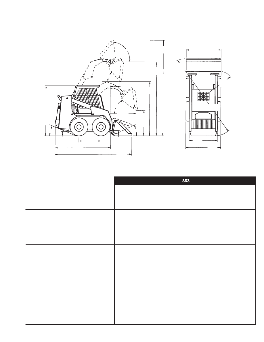
LOADER SPECIFICATIONS
Loader Dimensions
•
Dimensions are given for loader equipped with standard tires and dirt bucket.
Dimensions may vary with other types. All dimensions are shown in inches. Respective
metric dimensions are given in millimeters enclosed by parentheses.
•
Where applicable, specifications conform to SAE/ISO standards and are subject to
change without notice.
This loader was designed without counterweights or ballasts. Changes of structure or weight distribution of
the loader can cause changes in control and steering response and can cause failure of the loader parts.
MC–1113
95
o
153.5
(3899)
40
o
119.6
(3038)
93.07
(2364)
36.1
(917)
38.0
(965)
45
o
30
o
80.9
(2055)
*101.8
(2586)
38.6
(980)
8.0
(204)
128.7
(3269)
6.2
(157)
25
o
23.4
(594)
63.3
(1608)
76.7
(1948)
48.4
(1229)
61.5
(1562)
51.6
(1311)
60.8
(1544)
* Overall Length W/O Bucket
853, 853H Loader
–9–3–
Service Manual

Hydraulic System
Pump
Engine driven gear type
. . . . . . . . . . . . . . . . . . . . . . . . . . . . . .
Pump Capacity
18.0 GPM (68,1 L/min.) @ 2750 RPM @ 1150 PSI (7929 kPa)
. . . . . . . . . . . . . . . . . . . . .
System Main Relief
2550–2600 PSI (17580–17924 kPa) @ Quick Couplers
. . . . . . . . . . . . . . . . . .
Filters (charge & implement)
Full flow replaceable 4 micron synthetic medial element
. . . . . . . . . .
Hydraulic Cylinders
Doubleacting
. . . . . . . . . . . . . . . . . . .
Bore Diameter:
Lift Cylinder (2)
2.25 (57,2)
. . . . . . . . . . . . . . . . . . . .
Tilt Cylinder (1)
3.25 (82,6)
. . . . . . . . . . . . . . . . . . . .
Rod Diameter:
Lift Cylinder (2)
1.50 (38,1)
. . . . . . . . . . . . . . . . . . . .
Tilt Cylinder (1)
1.50 (38,1)
. . . . . . . . . . . . . . . . . . . .
Stroke:
Lift Cylinder (2)
33.5 (851)
. . . . . . . . . . . . . . . . . . . .
Tilt Cylinder (1)
18.9 (480)
. . . . . . . . . . . . . . . . . . . .
Control Valve
3–spool, open center, series type W/float detent on lift,
. . . . . . . . . . . . . . . . . . . . . . .
single spool electrical control front auxiliaries.
Fluid Lines
SAE standard tubes, hoses & fittings
. . . . . . . . . . . . . . . . . . . . . . . . .
Hydraulic Function Time:
Raise Lift Arms to Maximum Height
4.0 Seconds
. . . .
Lower Lift Arms from Maximum Height
3.4 Seconds
.
Move Empty Bucket to Dump Position
2.3 Seconds
.
Move Bucket to Retracted Position
1.9 Seconds
. . . .
Fluid Type
Bobcat Fluid (P/N 6563328); If fluid is not available, use
. . . . . . . . . . . . . . . . . . . . . . . . . . .
10W–30/10W–40 Class SE, SF, SG Motor Oil for temperatures above 0
o
F (–18
o
C)
& 5W–30 Motor Oil for temperatures below 0
o
F (–18
o
C).
Electrical
Alternator
Belt drive, 55 amps. Open
. . . . . . . . . . . . . . . . . . . . . . . . . .
Battery
12 volt, 700 cold crank amps. @ 0
o
F (–18
o
C) 170 min. reserve capacity
. . . . . . . . . . . . . . . . . . . . . . . . . . . .
Starter
12 volt
,
3.7 HP (2,8 kW)
. . . . . . . . . . . . . . . . . . . . . . . . . . . . .
Drive System
Transmission
Tandem hydro. pumps infinitely variable, driving 2 fully reversing hydrostatic motors
. . . . . . . . . . . . . . . . . . . . . . .
Final Drive
Gear Reduction & #100 HS roller chain &
. . . . . . . . . . . . . . . . . . . . . . . . .
sprockets in sealed chaincase with oil lubrication
Total Engine to Wheel Reduction
47:27:1
. . . . . .
Capacities
Cooling System
22 qts. (20,8 L)
. . . . . . . . . . . . . . . . . . . . .
Fuel
25 gals. (95 L)
. . . . . . . . . . . . . . . . . . . . . . . . . . . . . . .
Engine Oil W/Filter
8 qts. (7,6 L)
. . . . . . . . . . . . . . . . . .
Hydraulic Reservoir
15.5 qts. (14.7 L)
. . . . . . . . . . . . . . . . . .
Hydraulic/Hydrostatic System
8 gals. (30,3 L)
. . . . . . . . .
Chaincase Reservoir
9 gals. (34,1 L)
. . . . . . . . . . . . . . . .
Tires
Standard
8.25–15, 6 Ply Rating, Nylon with Bar Lug Tread
. . . . . . . . . . . . . . . . . . . . . . . . . . .
Pressure
45–50 PSI (310–345 kPa)
. . . . . . . . . . . . . . . . . . . . . . . . . .
Flotation
12:00–16,5, 6 Ply Rating, Nylon with Sure Grip Lug
. . . . . . . . . . . . . . . . . . . . . . . . . . .
Pressure
30–35 PSI (207–240 kPa)
. . . . . . . . . . . . . . . . . . . . . . . . . .
LOADER SPECIFICATIONS (Cont’d)
–9–4–
853, 853H Loader
Service Manual
Нет комментариевНе стесняйтесь поделиться с нами вашим ценным мнением.
Текст