Loader Bobcat 853, 853H. Manual — part 77
12 volt supply and
BOSS failure.
Sensor No Signal or
No RPM’s.
Lack of 5.0 volts
regulated power.
Low voltage (5.0)
triggered reset.
The display is not fault
tolerant. Also can be
an indication of poor
internal connections.
Bad display or BOSS
is not communicating.
Temperature related
shutdown codes
when no heating
occurs.
Intermittent code of
ES6 while engine
running.
Display is dead – No
Icons, Bar Graphs,
Hourmeter.
During an active
WARNING display,
reset occurs and the
hourmeter becomes
all zero’s.
Garbled message,
missing segments,
etc.
After glow sequence
or after a WARNING
goes away, the Icon
remains ON.
No Bar Graphs, no
Hours.
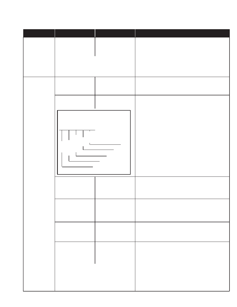
LCD DISPLAY
CONNECTOR
A B C D E
Ground
Positive Com. 3.5 to 4 Volts
5.0 Volts Regulated Power
Orange
NOTE: The display has caused the
problem by locking the
communication lines and
stopping communications from
the BOSS.
1.
Check stored defects with the BOSS tool.
*2.
If defect list has EC1, HC1, EC2.1, HC2. EP3,
EP7, HP7, B2.2, low fuel, Fuel 7 and last
occurrence hr. readings are within a hundredth,
the BOSS is defective and must be replaced.
3.
Using a voltmeter, check the alternator output.
1.
ES6 will occur if the loader is stalled or shutdown
during run cycle. The code is generated due to the
lack of RPM and the existence of residual
pressure in the system.
1.
Check pin A for 5.0 volts. If 5.0 volts is present
replace the display.
2.
If no power exists at pin A, install BOSS backup
to confirm the BOSS system.
3.
If the problem still exists, check the harness for
continuity.
1.
Turn the ignition switch OFF. Re–starting will
return hourmeter reading.
2.
If re–starting will not return hourmeter reading,
check pins B & C as stated in Step 5 below.
1.
Turn the ignition switch OFF and re–start. A
fault is an invalid message that the display tries
to display. Generally a fault occurs if
communications of two messages are combined
on the display.
1.
Turn the key OFF and re–start.
1.
Plug in the BOSS tool and start the engine.
2.
If data is being received by the BOSS tool, the
BOSS unit is not the cause of the problem.
3.
If no data is received at the BOSS tool.
disconnect the LCD display.
*4.
If messages are now received at the tool, the
display is the problem. If problem still exists go to
Step 5.
5.
Check pins B & C for signal.
6.
If there is no signal, install BOSS backup unit.
7.
If the problem still exists, check the harness for
continuity.
TROUBLESHOOTING THE BOSS
®
& LCD DISPLAY
Chart
NOTE: You may have some or all of the
codes listed. You will have high
temps, high press, low voltage
and low fuel.
BOSS
LCD Display
12 Volt – Back Light
Negative Com. .5 to 1.5 Volts
Black
Orange
Purple/Red
Purple/White
Power Display Operation
TO CORRECT SYMPTOM
INDICATES
SYMPTOM
SUBJECT
*
*
853,853H Loader
–8–7–
Service Manual
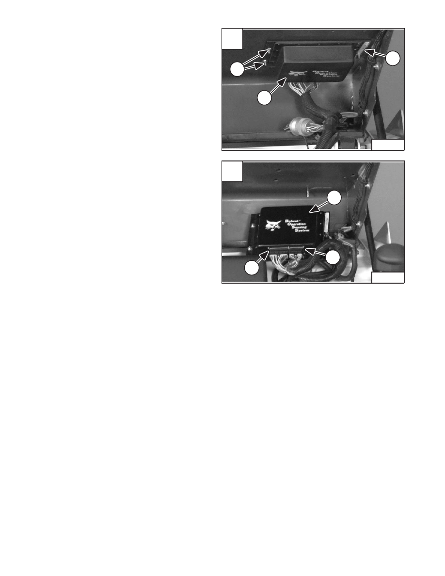
BOSS
®
UNIT
Removal And Installation
Raise the loader operator cab. (See Page 1–1.)
Loosen the nuts (Item 1) [A] from the sensing system unit
(Item 2) [A].
Slide the unit forward in the mounting slots and remove
it from the operator cab.
Remove the two connectors (Item 1) [B] from the sensing
system unit (Item 2) [B].
Installation: Put the heads of the mounting bolts into the
slots of the operator cab and slide the unit back into place.
Tighten the three mounting nuts to 80–90 in.–lbs. (9–10
Nm) torque.
A
P–04043
1
2
1
–8–8–
853, 853H Loader
Service Manual
B
P–04042
2
1
1
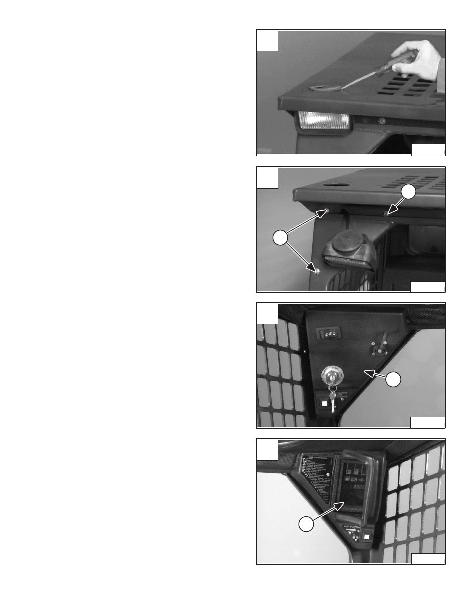
BOSS
®
INSTRUMENT PANEL
Removal And Installation
Pry the rubber light mount from the operator cab (both
sides) [A].
Lower the light from the operator cab and remove the
three panel mounting bolts (Item 1) [B] (both sides.)
Pull the left panel (Item 1) [C] down from the operator cab.
Installation: Do not overtighten the panel mounting bolts
to prevent stripping the threaded holes of the panels.
Disconnect the wire harness connectors from the panel
and remove the panel.
Remove the three mounting bolts and pull the right panel
(Item 1) [D] down from the operator cab.
Installation: Do not overtighten the panel mounting bolts
to prevent stripping the threaded holes of the panels.
Disconnect the wire harness connectors from the panel
and remove the panel.
A
P–03995
C
P–03958
1
D
P–03959
1
853,853H Loader
–8–9–
Service Manual
853, 853H Service Manual #6720755 – BICS System Section
B
P–03955
1
1

–8–10–
853, 853H Loader
Service Manual
Нет комментариевНе стесняйтесь поделиться с нами вашим ценным мнением.
Текст