Loader Bobcat 853, 853H. Manual — part 69

MAIN BEARINGS (Cont’d)
Installation
Check the bearing spread as listed [A].
Limit – 2.93 inch (74,5 mm)
Check to see if the bearing has enough tension, so that
finger pressure is needed to fit the bearing into the cap
[B].
Check the crankshaft journals before installing the main
bearings. (See Page 7–68.)
Make sure to position the bearing halves in their correct
locations [C].
Lubricate the new bearings. Install them by putting the
end without the tab into the block and rotating the
crankshaft until the tab is on its seat.
Install the other bearing half in the bearing cap. Lubricate
the bearing and install the cap on the engine block.
Lubricate the bolts, install them finger tight only.
Install the center main bearing and thrust washers [D].
The thrust washer must be installed so that their oil
grooves are turned to the rotating face of the crankshaft.
Repeat the procedure until all the main bearings and caps
are installed.
A
B–08241
C
B–08254
No Oil Groove
and Hole
(Lower Side)
With Oil Hole
and Groove
(Upper Side)
Fit Correctly
D
B–08255
853, 853H Loader
–7–65–
Service Manual
B
B–08242
MAIN BEARINGS (Cont’d)
Installation (Cont’d)
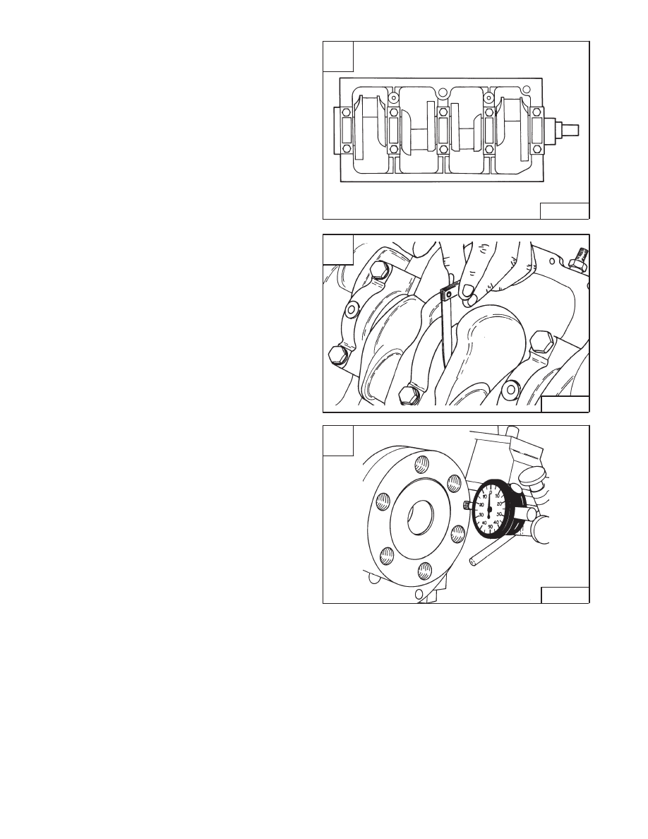
Tighten the crankshaft bearing cap bolts in the correct
sequence [A].
Torque – 116–130 ft.–lbs. (157–176 Nm).
Crankshaft End Play
The end play can be checked by either a feeler gauge [B]
or dial indicator [C].
Standard End Play
0.004 inch (0,10 mm)
. . . . . . . . . . . .
Limit
0.012 inch (0,30 mm)
. . . . . . . . . . . . . . . . . . . . . . . .
The fitting of oversize thrust washer can be used to
correct the end play if it is over the specifications.
A
B–08257
10
6
2
3
7
8
4
1
5
9
C
B–03291
–7–66–
853, 853H Loader
Service Manual
B
B–03347

CRANKSHAFT
Removal And Installation
Remove the oil pan. (See Page 7–81.)
Remove the oil pump. (See Page 7–82.)
Remove the crankshaft pulley, timing gearcase cover and
timing gears. (See Page 7–71.)
Remove the flywheel.
Remove the connecting rod cap. (See Page 7–57.)
Remove the main bearing cap. (See Page 7–64.)
Lift the crankshaft out of the engine block.
Checking Tuffriding (Soft Nitriding) Coating
Clean the crankshaft thoroughly using an organic solvent.
Make sure there is no oil or grease in the area to be tested.
Using a glass rod, put a drop of cupric ammonium chloride
5/10% solution at the test location [A].
If no change takes place after an interval of 30–40
seconds, the crankshaft can be re–used if within
specifications.
Replace the crankshaft, if within the 30–40 seconds, the
original color of the solution (light blue in color) becomes
transparent where the test solution was dropped and will
discolor to a copper color.
Immediately after the test is completed, wipe off the area
with a cloth and thoroughly rinse with water.
NOTE: Since the crankshaft is tuffride coated it
cannot be reground.
Checking The Crankshaft
Check the crankshaft connecting rod journals [B].
Standard – 2.0833–2.0839 inch (52,915–52,930 mm)
Limit – 2.0829 inch (52,906 mm)
A
B–08243
The sliding surface
of the pin
or journal
The portion to be tested
shall be held horizontally so
as not to let the test
solution flow.
Approximately
0.393 inch (10 mm)
No testing solution
near the oil hole.
853, 853H Loader
–7–67–
Service Manual
B
B–08244
CRANKSHAFT (Cont’d)
Checking The Crankshaft (Cont’d)
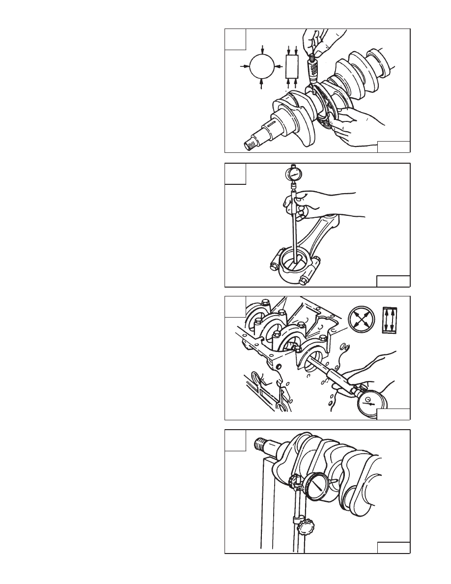
Check the crankshaft main bearing journals [A].
Standard – 2.7526–2.7532 inch (69,917–69,932 mm)
Limit – 2.7524 inch (69,910)
Check the clearance between connecting rod bearing
and crankshaft journal [B].
Install the bearing and cap and tighten nuts to 58–65
ft.–lbs. (79–88 Nm) torque. Put oil on the bearing and
measure.
Nominal Diameter – 2.09 inch (53,0 mm)
Clearance between journal and bearing:
Standard – 0.0011–0.0026 inch (0,029–0,066 mm)
Limit – 0.004 inch (0,10 mm)
Check the clearance between main bearings and
crankshaft journals [C].
Install the main bearing and caps and tighten the bolts to
116–130 ft.–lbs. (157–176 Nm) torque. Put oil on the main
bearings and measure.
Nominal Diameter – 2.76 inch (70,0 mm)
Clearance between the journal and bearing:
Standard – 0.0014–0.0031 inch (0,035–0,080 mm)
Limit – 0.0043 inch (0,11 mm)
Check the crankshaft run–out [D].
Standard – 0.0019 inch (0,05 mm) or less
Limit – 0.003 inch (0,08 mm)
A
B–08246
C
B–08247
D
B–08248
–7–68–
853, 853H Loader
Service Manual
B
B–08245
Нет комментариевНе стесняйтесь поделиться с нами вашим ценным мнением.
Текст