Loader Bobcat 853, 853H. Manual — part 67
PISTON AND CONNECTING ROD
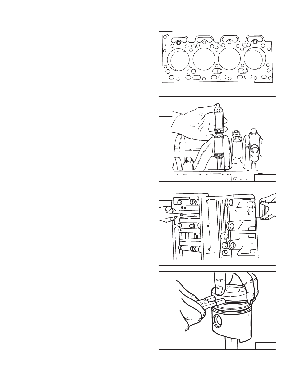
Removal
Remove the cylinder head. (See Page 7–51.)
Remove the oil pan. (See Page 7–81.)
Remove the ridge and carbon deposits at the top of the
cylinder bore with a ridge reamer.
Make sure the pistons have identification marks [A].
Rotate the crankshaft until a pair of connecting rods are
at the bottom dead center. Make sure the connecting rod
caps and the rods have identification marks.
Remove the nuts and remove the bearing caps [B].
NOTE: If the bearings are to be used again, they
must be identified so they are returned to
their original location.
Using a hammer handle, push the piston and rod out of
the block [C].
After the pair has been removed, rotate the engine
crankshaft and remove the other pair of pistons.
Disassembly
Remove the rings from the pistons [D].
A
B–03248
1
2
3
4
F
F
F
F
C
B–08909
D
B–08194
853, 853H Loader
–7–57–
Service Manual
B
A–02344

PISTON AND CONNECTING ROD (Cont’d)
Disassembly (Cont’d)
Remove the piston pin snap ring [A].
Drive out the piston pin using a brass rod [B].
Checking
Clean all the parts in clean solvent.
Check the clearance of the new rings in the piston
grooves [C].
Standard
Limit
1st
0.0035–0.0049 inch
0.006 inch
Compression
(0,09–0,125 mm)
(0,15 mm)
2nd
0.002–0.0033 inch
0.006 inch
Compression
(0,05–0,085 mm)
(0,15 mm)
Oil
0.001–0.003 inch
0.006 inch
(0,03–0,07 mm)
(0,15 mm)
Check the piston diameter [D].
Pistons are available in two sizes.
Piston Grade A
3.6608–3.6616 inch
(92,985–93,004 mm)
Piston Grade C
3.6616–3.6624 inch
(93,005–93,024 mm)
Refer to parts fiche when ordering pistons, piston rods
and cylinder liners.
A
B–08195
C
B–08228
D
B–08227
2.9 ”
(74 mm)
–7–58–
853, 853H Loader
Service Manual
B
P–08196

PISTON AND CONNECTING ROD (Cont’d)
Checking (Cont’d)
Check the ring gap in the cylinder bore [A].
Standard
Limit
Compression
0.008–0.016 inch
0.059 inch
(0,20–0,40 mm)
(1,50 mm)
Oil
0.004–0.012 inch
0.059 inch
(0,10–0,30 mm)
(1,50 mm)
Check the piston pin diameter [B].
Standard – 1.220 inch (31,0 mm)
Limit – 1.219 inch (30,97 mm)
Check the clearance between piston pin and piston pin
bore [C].
Clearance – 0.00008–0.00006 inch
(0,002–0,015 mm)
Check the connecting rod alignment [D].
Standard – 0.002 inch (0,50 mm) or less
Limit – 0.0079 inch (0,20 mm)
A
B–08229
C
B–08231
D
B–08232
853, 853H Loader
–7–59–
Service Manual
B
P–08230

PISTON AND CONNECTING ROD (Cont’d)
Checking (Cont’d)
Check the connecting rod small end bushing [A].
Standard – 1.2208–1.2211 inch (31,008–31,015 mm)
Check the clearance between the piston pin and
connecting rod [B].
Standard – 0.0003–0.00079 inch (0,008–0,02 mm)
Limit – 0.0002 inch (0,5 mm)
Replace the small end bushing if not within specifications
using a hydraulic press [C].
After installation of a new bushing, finish the bushing bore
to the correct specifications [D].
A
B–08233
C
B–08200
D
B–08203
–7–60–
853, 853H Loader
Service Manual
B
P–08230
Нет комментариевНе стесняйтесь поделиться с нами вашим ценным мнением.
Текст