Loader Bobcat 853, 853H. Manual — part 40
REDUCTION GEARCASE (Cont’d)
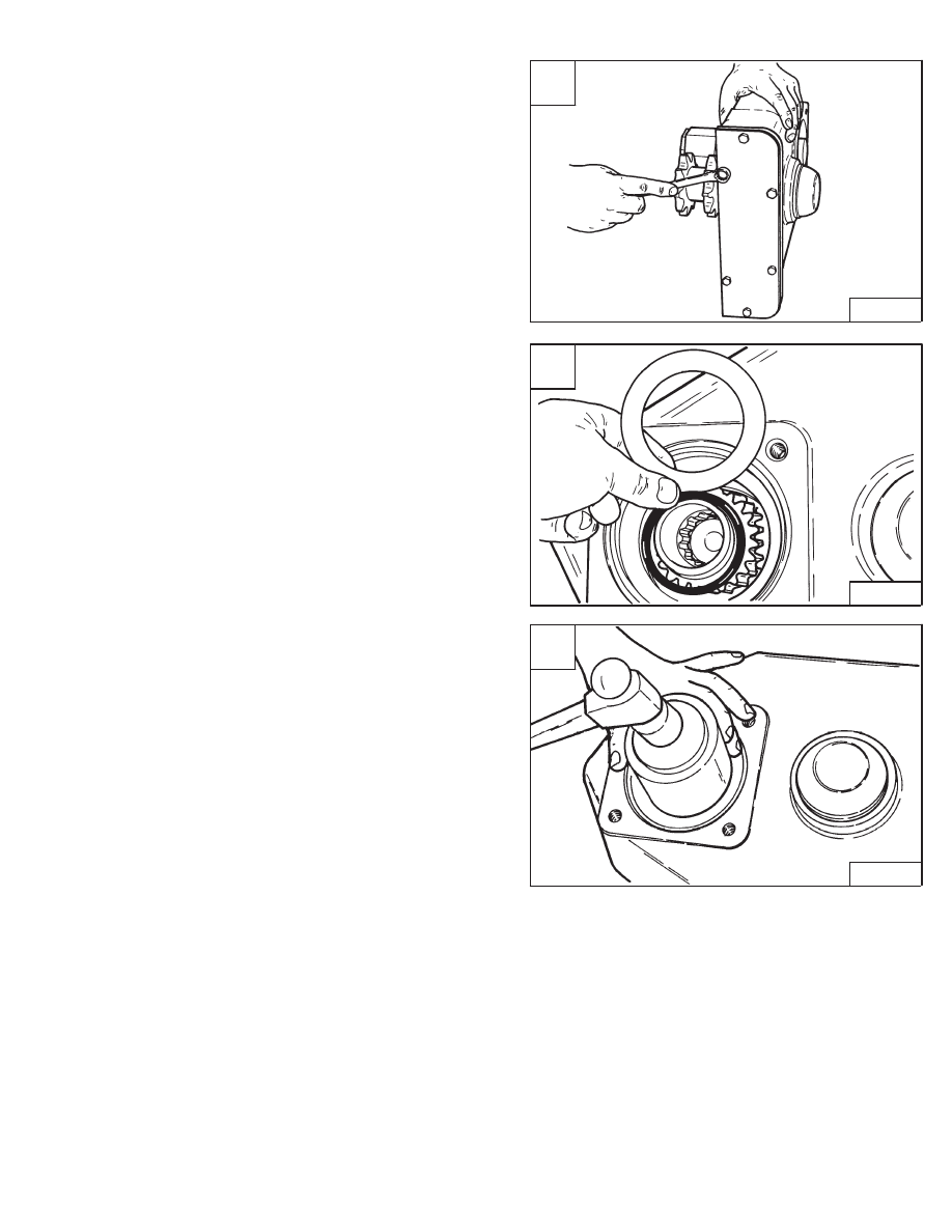
Assembly (Cont’d)
Install the end plate bolts and tighten to 13–14 ft.–lbs.
(Nm) torque [A].
Install a new quad ring. Install the backup washer [B].
Install the new seal using the seal installation tool [C].
A
B–08705
C
B–08734
853, 853H Loader
–4–25–
Service Manual
853, 853H Service Manual #6720755 – Drive System Section Part 1 of 2
B
B–08675

DRIVE CHAIN
Removal And Installation
NOTE: It is necessary to remove the rear axle and
drive chain [A]. If the front chain has to be
removed.
Lift and block the loader. (See Page 1–1.)
Raise the operator cab. (See Page 1–1.)
Removing the front panel/steering lever assembly. (See
Page 3–1.)
Remove the center chaincase cover. (See Page 4–5.)
Remove the front and rear chaincase cover. (See Page
4–8.)
Remove the fluid from the chaincase. (See Page 4–27.)
Remove the rear axle. (See Page 4–11.)
Never work on a machine with the lift arms up
unless the lift arms are secured by an approved
lift arm support device. Failure to use an
approved lift arm support device can allow the
lift arms or attachment to fall and cause injury
or death.
W–2059–0598
A
P–04805
Front Drive
Chain
Rear Drive
Chain
–4–26–
853, 853H Loader
Service Manual

CHAINCASE FLUID
Removing The Fluid From The Chaincase
To drain the oil from the chaincase, remove the cover
(Item 1) [A] which is installed over the drain plug at the
rear of the chaincase.
Remove the drain plug (Item 1) [B] and drain the oil into
a container.
Check the drain plug and replace if necessary.
A
P–1616
1
853, 853H Loader
–4–27–
Service Manual
B
P–1619
1
MAIN
FRAME
853, 853H Loader
–5–1–
Service Manual
Page
Number
BOB–TACH
Bob–Tach Lever And Wedge
5–9
. . . . . . . . . . . . . . . . . . . . . . . . . . . . . . . . . . . . .
Bob–Tach Stops
5–10
. . . . . . . . . . . . . . . . . . . . . . . . . . . . . . . . . . . . . . . . . . . . . .
Removal And Installation
5–7
. . . . . . . . . . . . . . . . . . . . . . . . . . . . . . . . . . . . . . . . .
FUEL TANK
Fuel Level Sender
5–16
. . . . . . . . . . . . . . . . . . . . . . . . . . . . . . . . . . . . . . . . . . . . .
Inlet Screen
5–16
. . . . . . . . . . . . . . . . . . . . . . . . . . . . . . . . . . . . . . . . . . . . . . . . . .
Removal And Installation
5–15
. . . . . . . . . . . . . . . . . . . . . . . . . . . . . . . . . . . . . . .
LIFT ARMS
Removal And Installation
5–11
. . . . . . . . . . . . . . . . . . . . . . . . . . . . . . . . . . . . . . . .
OPERATOR CAB
Removal And Installation
5–5
. . . . . . . . . . . . . . . . . . . . . . . . . . . . . . . . . . . . . . .
OPERATOR CAB GAS CYLINDER
Disassembly And Assembly
5–4
. . . . . . . . . . . . . . . . . . . . . . . . . . . . . . . . . . . .
Removal And Installation
5–3
. . . . . . . . . . . . . . . . . . . . . . . . . . . . . . . . . . . . . . .
REAR DOOR
Bumper Removal And Installation
5–14
. . . . . . . . . . . . . . . . . . . . . . . . . . . . . . .
Door Latch And Catch Adjustment
5–14
. . . . . . . . . . . . . . . . . . . . . . . . . . . . . . .
Door Latch Removal And Installation
5–14
. . . . . . . . . . . . . . . . . . . . . . . . . . . .
Hood Removal And Installation
5–14
. . . . . . . . . . . . . . . . . . . . . . . . . . . . . . . . .
Removal And Installation
5–13
. . . . . . . . . . . . . . . . . . . . . . . . . . . . . . . . . . . . . . .
REAR GRILL
Removal And Installation
5–12
. . . . . . . . . . . . . . . . . . . . . . . . . . . . . . . . . . . . . . .
MAIN FRAME
Нет комментариевНе стесняйтесь поделиться с нами вашим ценным мнением.
Текст