Loader Bobcat 853, 853H. Manual — part 41

OPERATOR CAB GAS CYLINDER
Removal And Installation
Cylinder contains high pressure gas. Do not
open. Opening cylinder can release rod and
cause injury or death.
W–2113–0288
Remove the operator cab stop (Item 1) [A] (both sides).
NOTE: Be careful not to break the rear window when
the cab is raised after the cab stops are
removed.
Raise the operator cab (See Page 1–1).
Remove the nuts (Item 1) [B] from the gas cylinder
mounting bracket.
Move the mounting bracket to relieve any remaining
tension on the gas cylinder [C].
Remove the cotter pin (Item 1) [D] from the top pivot pin.
Remove the pivot pin and bushing from the gas cylinder.
Remove the gas cylinder.
Never work on a machine with the lift arms up
unless the lift arms are secured by an approved
lift arm support device. Failure to use an
approved lift arm support device can allow the
lift arms or attachment to fall and cause injury
or death.
W–2059–0598
C
CD–15016
D
CD–15173
1
A
CD–15014
1
853, 853H Loader
–5–3–
Service Manual
B
CD–15015
1
OPERATOR CAB GAS CYLINDER (Cont’d)
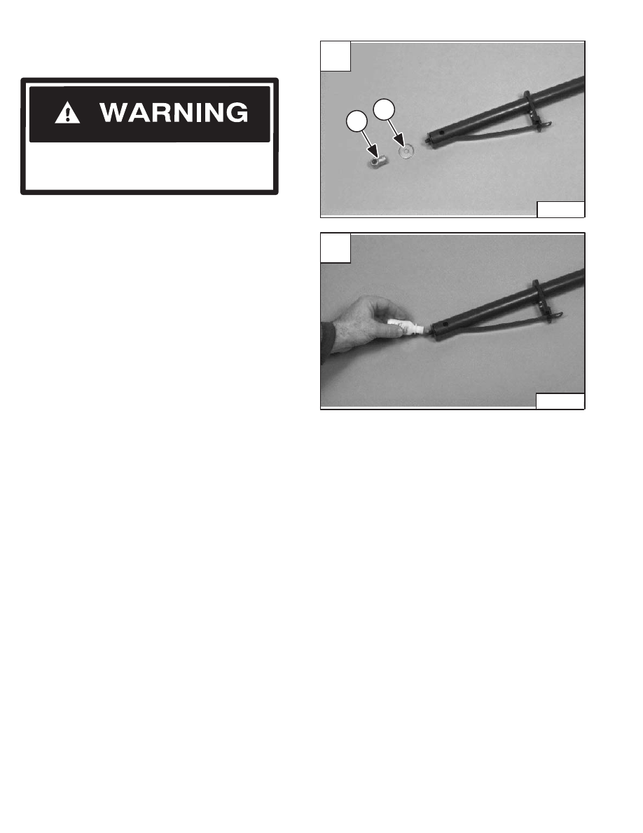
Disassembly And Assembly
Remove the clevis (Item 1) [A] and washer (Item 2) [A]
from the end of the gas cylinder.
Remove the gas cylinder from the outer housing.
Assembly: Install a replacement cylinder inside the
cylinder housing.
Apply a small amount of LOCTITE #242 adhesive on the
threads of the cylinder rod [B].
Reinstall the washer and clevis on the cylinder rod.
Cylinder contains high pressure gas. Do not
open. Opening cylinder can release rod and
cause injury or death.
W–2113–0288
A
P–01008
1
2
–5–4–
853, 853H Loader
Service Manual
B
P–01006
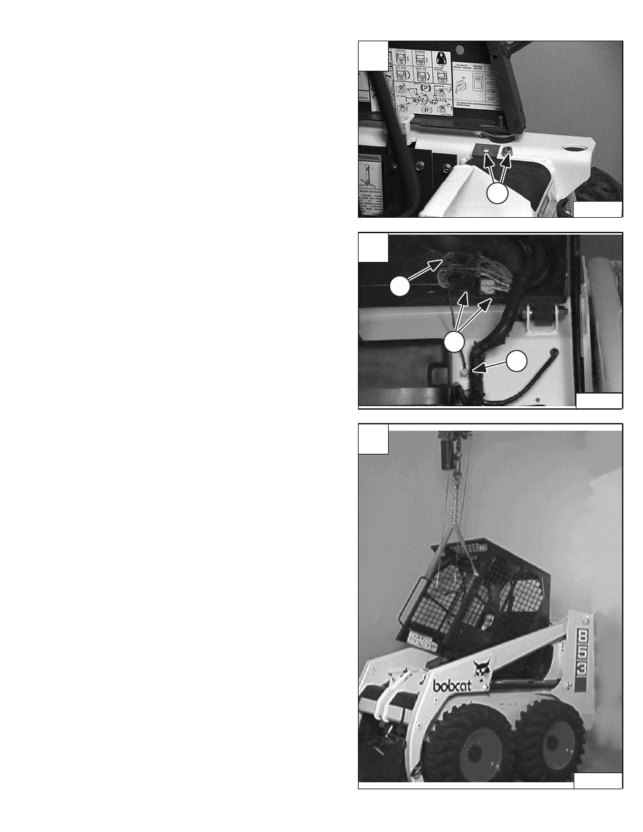
OPERATOR CAB
Removal And Installation
Remove the cab nut and holddown plate (Item 1) [A] (both
sides).
Installation: Tighten the nut to 40–50 ft.–lbs. (54–68 Nm)
torque.
Remove both gas cylinders (Page 5–7).
Disconnect the wiring harness connectors (Item 1) [B].
Disconnect the ground wire (Item 2) [B].
Connect a chain hoist to the operator cab grab handles
and lower the operator cab when the gas cylinders are
disconnected [C].
Revised June 97
A
CD–15125
1
B
P–00883
1
2
1
C
P–05051
853, 853H Loader
–5–5–
Service Manual
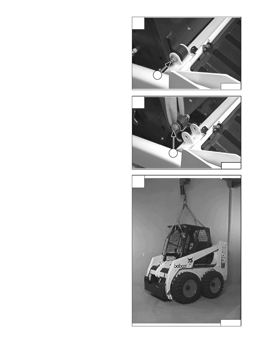
OPERATOR CAB (Cont’d)
Removal And Installation (Cont’d)
Remove the nut (Item 1) [A] from the pivot bolt (both
sides).
Installation: Tighten the pivot bolt and nut to 25–35
ft.–lbs. (34–47 Nm) torque.
Remove the pivot bolt (both sides).
Move the operator cab forward a small amount for
clearance at the pivot mounting brackets [B].
Install the pivot bolt, washer (one on each side) and nut
(Item 1) [B] (both sides).
Install the sling under the pivot bolt and pivot of the
operator cab [B].
Connect the slings to a chain hoist and remove the
operator cab from the loader [C].
C
P–05050
A
P–05048
1
–5–6–
853, 853H Loader
Service Manual
B
P–05049
1
Нет комментариевНе стесняйтесь поделиться с нами вашим ценным мнением.
Текст