Loader Bobcat 773. Manual — part 98
CRANKSHAFT AND BEARINGS (Cont’d)
Servicing The Crankshaft And Bearings (Cont’d)
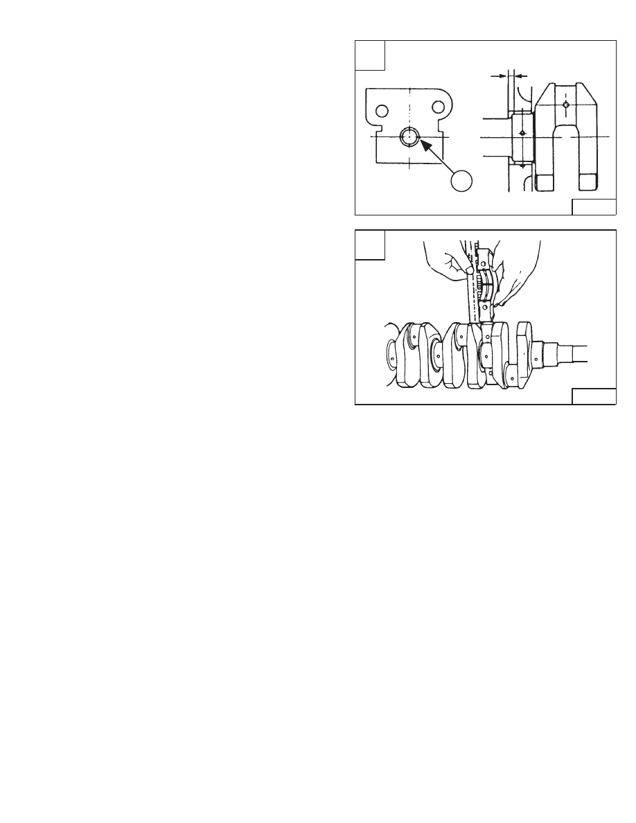
Remove the front bearing (Item 1) [A] with the special
removal tool.
Installation: Clean the new bearing and bore, apply oil
on them. Install the new bearing with the installation driver
tool [A].
Clean the crankshaft journal and bearing. Put a strip of
press gauge on the center journal.
Install the main bearing case halves and tighten the bolts.
Remove the bearing case halves.
Measure the flattened press gauge [B].
If the clearance exceeds the allowable limit, replace the
crankshaft bearing.
Crankshaft Journal
O.D.
2.044–2.045 inches (51,92–51,94 mm)
. . . . . . . .
Bearing I.D.
2.046–2.048 inches (51,98–52,03 mm)
. .
Oil Clearance
0.002–0.004 inch (0,04–0,10 mm)
. . . . . .
Allowable Limit
0.008 inch (0,2 mm)
. . . . . . . . . . . . . . . . .
A
PI–10024
0.165–0.177’’
(4,2–4,5 mm)
1
773 BICS Loader
–7–71–
Service Manual
B
PI–10025
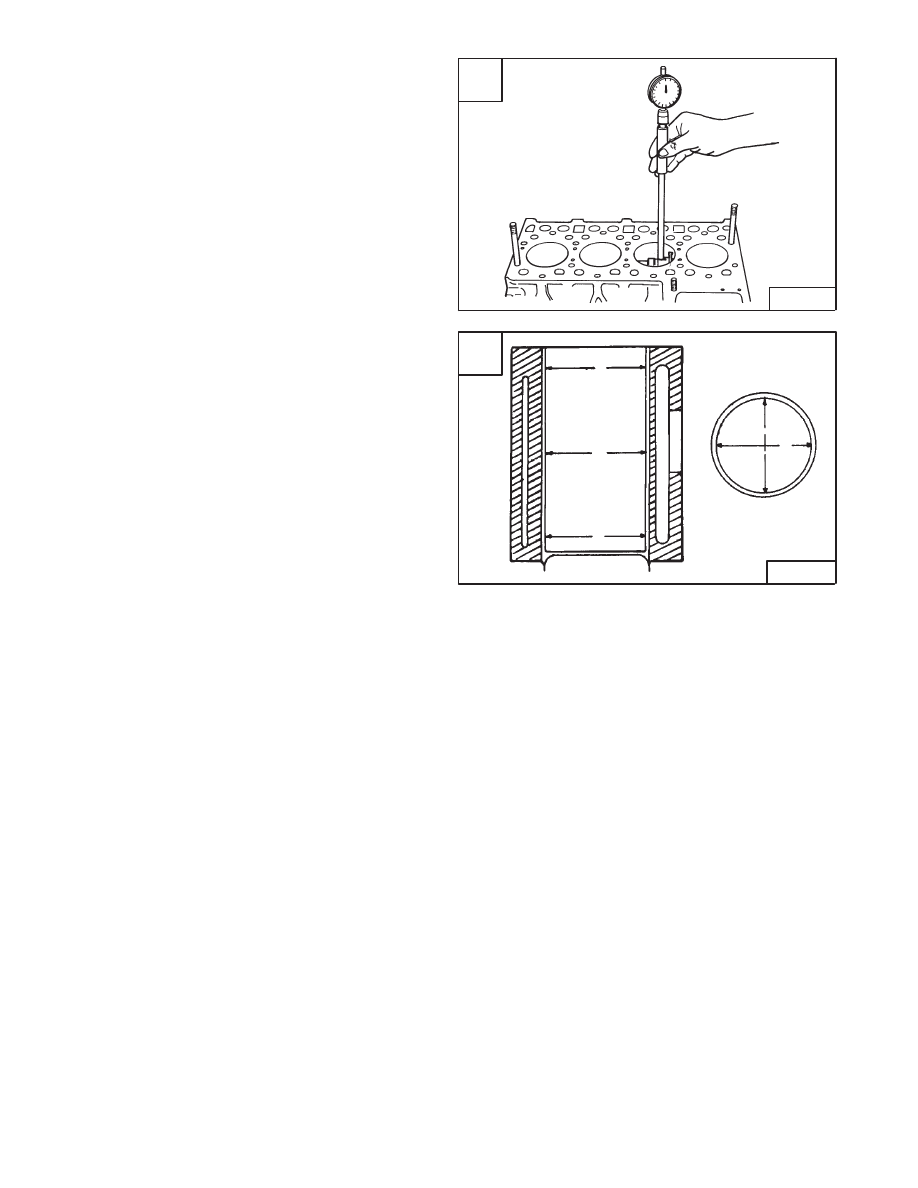
CYLINDER BORE
Checking The Cylinder Bore
Use a gauge to check the inside measurement of the
cylinder bore [A].
Measure the six points as shown in figure [B] to find the
maximum wear.
The specification is 3.425–3.426 inches (87,0–87,02
mm). The wear limit is +0.006 inch (+0,15 mm).
If the cylinder bore is not within specifications, re–bore the
cylinder for oversize piston.
A
B–04066
–7–72–
773 BICS Loader
Service Manual
B
A–02717
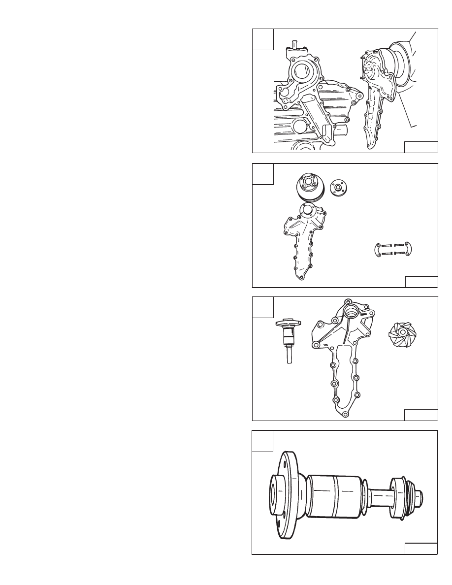
WATER PUMP
Disassembly And Assembly
Remove the water pump from the timing gearcase cover
[A].
Put the water pump in a vise and remove the nut [B].
Remove the pulley using a puller. Remove the key and
snap ring.
Drive the shaft out of the impeller side of the water pump
housing [C].
Install the new seals [D]. Install the shaft.
Installation: Put the water pump in a vise and tighten the
nut to 50–57 ft.–lbs. (68–77 Nm) torque. Always use a
new gasket when installing the water pump on the timing
gearcase cover.
A
B–05318
C
B–05325
D
A–02783
773 BICS Loader
–7–73–
Service Manual
B
B–05324
SYSTEMS
ANALYSIS
773 BICS Loader
–8–1–
Service Manual
SYSTEMS ANALYSIS
BOBCAT INTERLOCK CONTROL SYSTEM (BICS
™
)
(S/N 509648900 & Above
)
(S/N 509617300 & Avove)
Additional Inspection For Loaders With Advanced Hand Controls
8–3
. . . .
Inspecting Deactivation Of The Auxiliary Hydraulics System
(Engine STOPPED – Key ON)
8–3
. . . . . . . . . . . . . . . . . . . . . . . . . . . . . . . . .
Inspecting The Bics
™
System Controller
(Engine STOPPED – Key ON)
8–3
. . . . . . . . . . . . . . . . . . . . . . . . . . . . . . . . .
Inspecting The Seat Bar Sensors (Engine Running)
8–3
. . . . . . . . . . . . . . .
Inspecting The Traction Lock (Engine Running)
8–3
. . . . . . . . . . . . . . . . . . .
Inspecting The Lift Arm By–Pass Control
8–3
. . . . . . . . . . . . . . . . . . . . . . . . .
Additional Inspection For Loaders
8–3
. . . . . . . . . . . . . . . . . . . . . . . . . . . . . . .
Troubleshooting Chart
8–4
. . . . . . . . . . . . . . . . . . . . . . . . . . . . . . . . . . . . . . . . .
BOBCAT INTERLOCK CONTROL SYSTEM (BICS
™
)
(S/N 509648899 & Below
)
(S/N 509617299 & Below)
Inspecting The Deactivation Of The Auxiliary Hydraulics System
(Engine STOPPED – Key ON)
8–5
. . . . . . . . . . . . . . . . . . . . . . . . . . . . . . . . .
Inspecting The Bics
™
System Controller
(Engine STOPPED – Key ON)
8–5
. . . . . . . . . . . . . . . . . . . . . . . . . . . . . . . . .
Inspecting The Seat And Seat Bar Sensors (Engine Running)
8–5
. . . . . . .
Inspecting The Traction Lock (Engine Running)
8–5
. . . . . . . . . . . . . . . . . . .
Inspecting The Lift Arm By–Pass Control
8–5
. . . . . . . . . . . . . . . . . . . . . . . . .
Maintenance
8–6
. . . . . . . . . . . . . . . . . . . . . . . . . . . . . . . . . . . . . . . . . . . . . . . . .
Troubleshooting Chart
8–7
. . . . . . . . . . . . . . . . . . . . . . . . . . . . . . . . . . . . . . . . .
BOBCAT INTERLOCK CONTROL SYSTEM (BICS
™
)
Troubleshooting Guide
BICS Controller
8–8
. . . . . . . . . . . . . . . . . . . . . . . . . . . . . . . . . . . . . . . . . . . . . .
Seat Bar Sensor
8–11
. . . . . . . . . . . . . . . . . . . . . . . . . . . . . . . . . . . . . . . . . . . . .
Seat Sensor
8–10
. . . . . . . . . . . . . . . . . . . . . . . . . . . . . . . . . . . . . . . . . . . . . . . . .
Traction Lock
8–9
. . . . . . . . . . . . . . . . . . . . . . . . . . . . . . . . . . . . . . . . . . . . . . . .
BICS
™
SYSTEM CONTROLLER
Removal And Installation
8–15
. . . . . . . . . . . . . . . . . . . . . . . . . . . . . . . . . . . . . . .
ELECTRICAL/HYDRAULIC CONTROLS REFERENCE
Controls Identification Chart
8–28
. . . . . . . . . . . . . . . . . . . . . . . . . . . . . . . . . . . .
SEAT BAR SENSOR
BICS
™
Controller Seat Sensor Circuit Test
8–18
. . . . . . . . . . . . . . . . . . . . . . .
Removal And Installation
8–17
. . . . . . . . . . . . . . . . . . . . . . . . . . . . . . . . . . . . . . .
Seat Bar Sensor Test
8–16
. . . . . . . . . . . . . . . . . . . . . . . . . . . . . . . . . . . . . . . . . .
SEAT SENSOR
BICS
™
Controller Seat Sensor Circuit Test
8–14
. . . . . . . . . . . . . . . . . . . . . . .
Removal And Installation
8–13
. . . . . . . . . . . . . . . . . . . . . . . . . . . . . . . . . . . . . . .
Seat Sensor Test
8–12
. . . . . . . . . . . . . . . . . . . . . . . . . . . . . . . . . . . . . . . . . . . . . .
TRACTION LOCK
Removal And Installation
8–19
. . . . . . . . . . . . . . . . . . . . . . . . . . . . . . . . . . . . . . .
Page
Number
BOBCAT INTERLOCK CONTROL SYSTEM (BICS
™
)
Continued On Next Page
Revised Jan. 99
Нет комментариевНе стесняйтесь поделиться с нами вашим ценным мнением.
Текст