Loader Bobcat 773. Manual — part 99
–8–2–
773 BICS Loader
Service Manual
SYSTEMS ANALYSIS
Page
Number
BOBCAT OPERATION SENSING SYSTEM (BOSS
®
)
BOSS
®
DIAGNOSTIC TOOL
Procedure
8–21
. . . . . . . . . . . . . . . . . . . . . . . . . . . . . . . . . . . . . . . . . . . . . . . . . . . .
BOSS
®
INSTRUMENT PANEL
Removal And Installation
8–27
. . . . . . . . . . . . . . . . . . . . . . . . . . . . . . . . . . . . . . .
MONITOR SERVICE CODES
Alphabetic Codes
8–22
. . . . . . . . . . . . . . . . . . . . . . . . . . . . . . . . . . . . . . . . . . . . .
Numeric Codes
8–22
. . . . . . . . . . . . . . . . . . . . . . . . . . . . . . . . . . . . . . . . . . . . . . .
Service Codes
8–23
. . . . . . . . . . . . . . . . . . . . . . . . . . . . . . . . . . . . . . . . . . . . . . . .
OPERATION SENSING SYSTEM UNIT
Removal And Installation
8–26
. . . . . . . . . . . . . . . . . . . . . . . . . . . . . . . . . . . . . . .
RPM SENSOR
Adjustment
8–21
. . . . . . . . . . . . . . . . . . . . . . . . . . . . . . . . . . . . . . . . . . . . . . . . . . .
SENDER AND SENSOR
Service Checks
8–28
. . . . . . . . . . . . . . . . . . . . . . . . . . . . . . . . . . . . . . . . . . . . . . .
Component
8–28
. . . . . . . . . . . . . . . . . . . . . . . . . . . . . . . . . . . . . . . . . . . . . . . . . . .
TROUBLESHOOTING THE BOSS
®
& L.C.D. DISPLAY
Chart
8–25
. . . . . . . . . . . . . . . . . . . . . . . . . . . . . . . . . . . . . . . . . . . . . . . . . . . . . . . .
Revised Jan. 99
BOBCAT INTERLOCK CONTROL SYSTEM (BICS
™
)
(S/N 509648900 & Above) (S/N 509617300 & Above)
Inspecting The BICS
™
Controller
NOTE: Record what lights are blinking (if any) and
number of blinks. Refer to Page 8–4.
Inspecting The Seat Bar Sensor (Engine RUNNING)
Inspecting The Traction Lock (Engine RUNNING)
Inspecting The Lift Arm By–Pass Control
Inspecting Deactivation Of The Auxiliary Hydraulics
System (Engine STOPPED – Key ON)
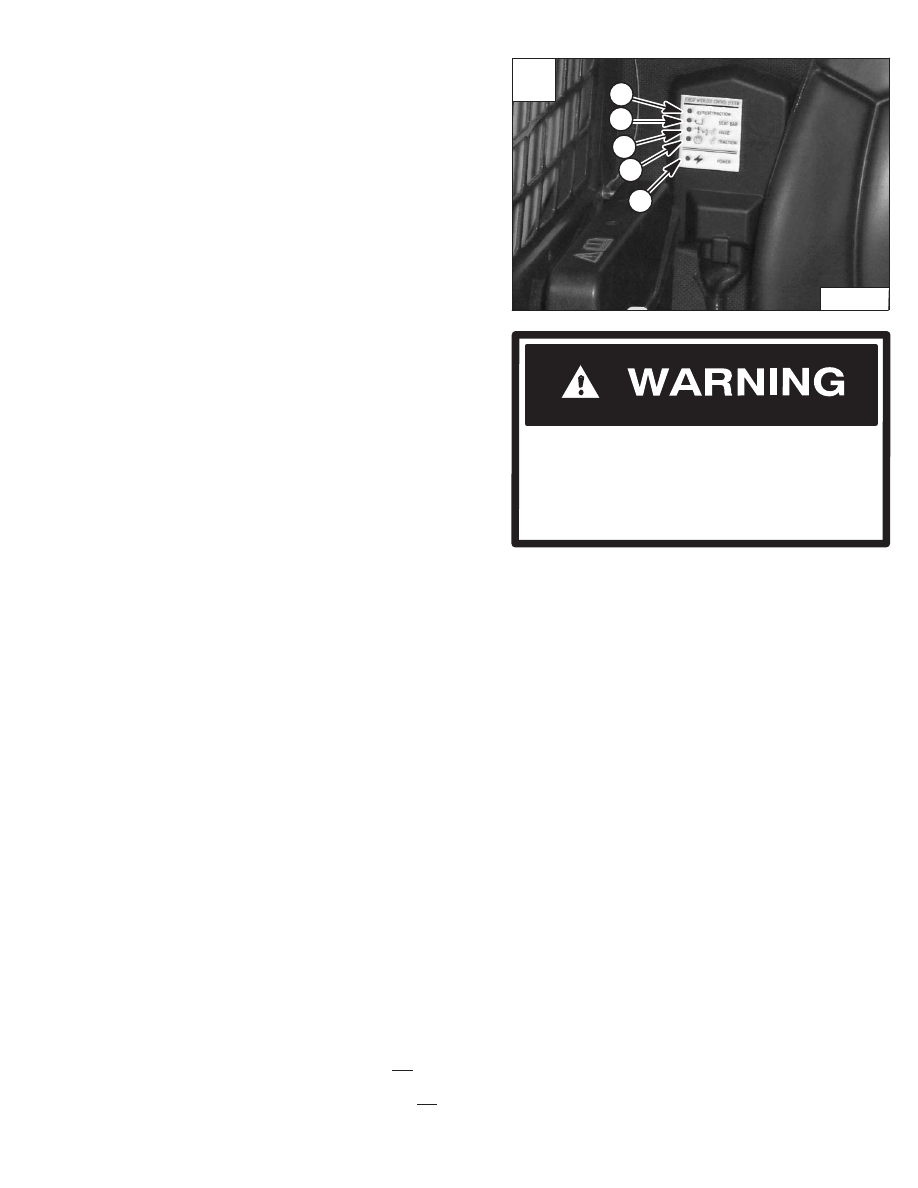
1. Sit in the operator’s seat. Turn key ON, lower the
seat bar and disengage the parking brake pedal.
Press the green PRESS TO OPERATE Button. All
five BICS controller lights should be ON (Items 1,
2, 3, 4 & 5) [A].
2. Engage the parking brake pedal and raise the seat
bar fully. System Activated (Item 1), Seat Bar (Item
2), Valve (Item 3) and Traction lights (Item 4) [A]
should be OFF.
3. Exit the loader and press Traction Lock Override
button. Traction light (Item 4) [A] should be ON.
Press override button again and Traction light
(Item 4) [A] should be OFF.
4. Sit in the operator’s seat. Lower the Seat Bar.
Press the green PRESS TO OPERATE Button.
Press the auxiliary hydraulics switch. The auxiliary
switch light will come ON. Raise the Seat Bar. The
light should be OFF.
5. Sit in the operator’s seat. Lower the seat bar.
Engage the parking brake pedal. Fasten the seat
belt.
6. Start the engine and operate at low idle. Press the
green PRESS TO OPERATE Button. While
raising the lift arms, raise the Seat Bar fully. The lift
arms should stop. Repeat using the tilt function.
7. Fasten the seat belt, disengage the parking brake
pedal, press the green PRESS TO OPERATE
Button and raise the Seat Bar fully. Move the
steering levers slowly forward and backward. The
Traction lock should be engaged. Lower the Seat
Bar. Press the green PRESS TO OPERATE
Button.
8. Engage the parking brake pedal and move the
steering levers slowly forward and backward. The
Traction lock should be engaged.
9. Raise the lift arms 6 feet (2 meters) off the ground.
Stop the engine.
Turn the lift arm by–pass control knob clockwise
1/4 turn. Then pull up and hold the lift arm by–pass
control knob until the lift arms slowly lower.
Additional Inspection For Loaders With Advanced
Hand Controls
10. Sit in the operator’s seat and fasten the Seat Belt.
Lower the Seat Bar, start the engine and press the
green PRESS TO OPERATE Button.
11. Raise the lift arms about 6 feet (2 meters) off the
ground.
12. Turn the key OFF and wait for the engine to come
to a complete stop.
13. Turn the key ON. Press the green PRESS TO
OPERATE Button, move the left hand control
toward the operator. The lift arms should not lower.
14. Move the right hand control away from the
operator. The bucket (or attachment) should not tilt
forward.
Revised Jan. 99
(Engine STOPPED – Key ON)
A
P–10157
1
2
3
4
5
773 BICS Loader
–8–3–
Service Manual
The Bobcat Interlock Control System (BICS)
must deactivate the lift, tilt and traction drive
functions. If it does not, contact your dealer for
service. DO NOT modify the system.
W–2151–0394
AVOID INJURY OR DEATH
System
PRESS TO OPERATE
PRESS TO OPERATE
Lift, tilt and traction
2
System Activated circuit shorted to
Activated
button is activated button not activated functions will not
battery voltage.*
operate.
3
System Activated circuit shorted to
ground.
Seat Bar
Seat Bar Down.
Seat Bar Up.
Lift, tilt and traction
2
Seat bar sensor circuit shorted to
functions will not
battery voltage*.
operate.
3
Seat bar sensor circuit shorted to
ground.
Valve
Control Valve
Control Valve
Lift and tilt functions
2
Valve output circuit shorted to battery
Can Be Used.
Cannot Be Used.
will not operate.
voltage*.
3
Valve output circuit shorted to ground.
3
Valve output circuit is not grounded.
Traction
Loader can be
Loader cannot be
Loader cannot be
1
Traction lock hold coil circuit is open.
moved forward
moved forward and
moved forward and
2
Traction lock hold coil circuit shorted
& backward.
backward.
backward.
to battery voltage*.
3
Traction lock hold coil circuit shorted
to ground.
4
Traction lock pull coil circuit is open.
5
Traction lock pull coil circuit is shorted
to battery voltage*.
6
Traction lock pull coil circuit is shorted
to ground.
Power
BICS Controller
BICS Controller is
Lift, tilt and traction
is operating
not operating
functions will not
N/A
N/A
correctly.
correctly.
operate.
Flashing Indicator Means System Problem
(See Your Bobcat Dealer for Service)
BOBCAT INTERLOCK CONTROL SYSTEM (BICS
™
) (S/N 509648900 & Above) (S/N 509617300 & Above) (Cont’d)
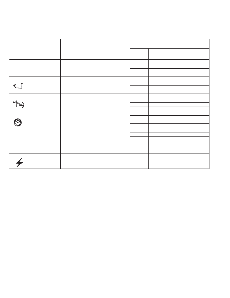
Troubleshooting Chart
The following list shows the effects which can happen to the loader, and the probable causes when the BICS Controller
lights are off or flashing. Have the service procedure performed ONLY BY QUALIFIED BOBCAT SERVICE PERSONNEL.
Effect on Operation
of Loader
Indicator
When Light Is
Number of
Light
Light ON
Light OFF
OFF
Flashes
Cause
NOTES:
(1) If the System Activated and/or seat bar sensor circuits are open, the corresponding lights will be OFF. If
one of the lights stay OFF, check the circuit for continuity.
(2) If all five lights flash repeatedly, the voltage supply is greater than 16 volts or less than 9 volts.
(3) Flashing patterns will repeat every 3.25 seconds.
* Normal BICS operating voltage is less than the electrical system voltage. If voltage is more, the circuit is shorted
to system voltage.
Revised June 01
–8–4–
773 BICS Loader
Service Manual
BOBCAT INTERLOCK CONTROL SYSTEM (BICS
™
)
(S/N 509648899 & Below) (S/N 509617299 & Below)
Inspecting The BICS
™
Controller
(Engine STOPPED – Key ON)
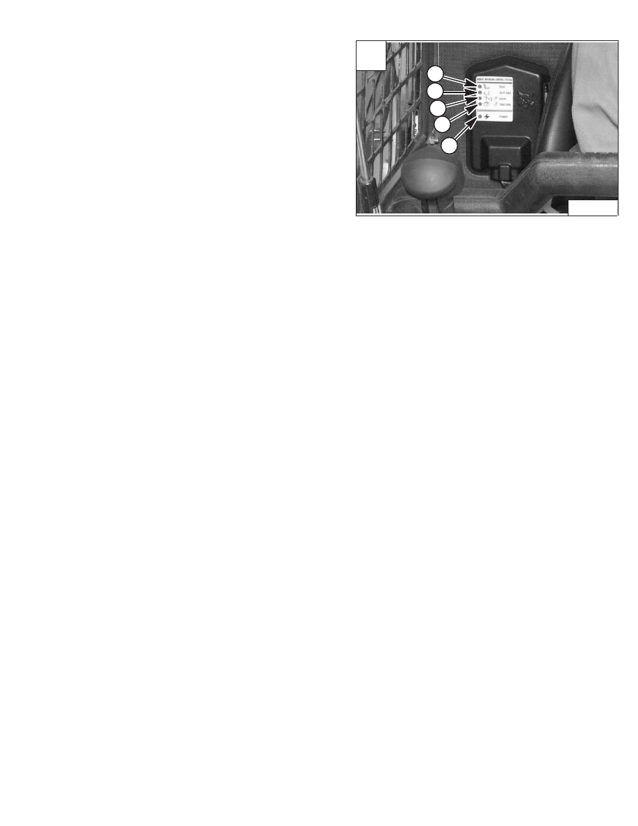
1. Sit in the operator’s seat. Turn key ON, lower the
seat bar and disengage the parking brake. All five
BICS Controller lights should be ON (Items 1, 2, 3,
4 & 5) [A].
2. Engage the parking brake, raise the seat bar fully.
Seat bar light (Item 2) [A], valve light (Item 3) [A]
and traction light (Item 4) [A] should be OFF.
3. Raise up slightly off the seat. Seat light (Item 1) [A]
should be OFF.
NOTE: Record what lights are blinking (if any) and
number of blinks. Refer to BICS
Troubleshooting Chart, Page 8–7.
4. Exit the loader and press traction lock override
button. Traction light (Item 4) [A] should be ON.
Press override button again and traction light (Item
4) [A] should be OFF.
Inspecting The Seat And Seat Bar Sensors
(Engine Running)
Inspecting The Traction Lock (Engine Running)
Inspecting The Lift Arm By–Pass Control
Early Models with or without mechanical Hand Controls
Raise the lift arms six feet (2 m) off the ground. Stop the
engine, pull and hold the by–pass control knob. Push the
toe of the left foot pedal or move the left hand control in
toward the operator (hand controls) and the lift arms
should lower slowly.
Later Models with or without machanical Hand Controls
Raise the lift arms six feet (2 m) off the ground. Stop the
engine. Turn the lift Arm By–Pass Control Knob clockwise
1/4 turn. Then pull up and hold the Lift Arm By–Pass
Control Knob until the lift arms slowly lower.
(Later Model Loaders Only) Inspecting Deactivation
Of The Auxiliary Hydraulics System
(Engine STOPPED – Key ON)
5. Sit in the operator’s seat. Lower the seat bar.
Press the auxiliary hydraulics auxiliary switch. The
auxiliary switch light will come ON. Raise the seat
bar. The light should be OFF.
6. Sit in the operator’s seat, lower the seat bar and
engage the parking brake. Fasten the seat belt.
7. Start the engine and operate at low idle. While
raising the lift arms, raise the seat bar fully. The lift
arms should stop. Repeat using the tilt function.
8. Fasten the seat belt, disengage the parking brake,
and raise the seat bar fully. Move the steering
levers slowly forward and backward. The traction
lock should be engaged. Lower the seat bar.
9. Engage the parking brake pedal and move the
steering levers slowly forward and backward. The
traction lock should be engaged.
Revised June 01
A
P–03760
1
2
3
4
5
773 BICS Loader
–8–5–
Service Manual
Нет комментариевНе стесняйтесь поделиться с нами вашим ценным мнением.
Текст