Loader Bobcat 773. Manual — part 124
HYDRAULIC CONTROL VALVE (Cont’d)
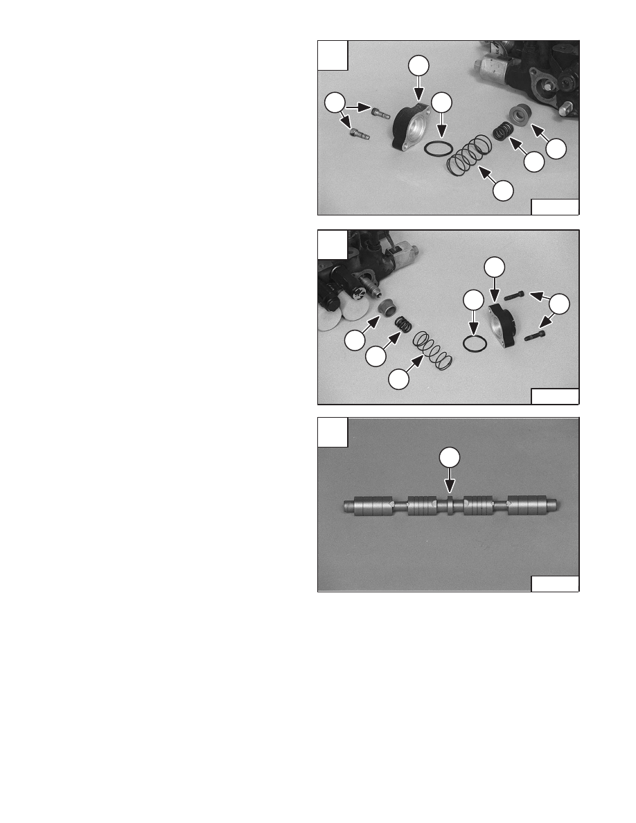
Auxiliary Spool
Remove the end cap screws (Item 1) [A] & [B].
Installation: Tighten the screws to 90–100 in.–lbs.
(10,2–11,3 Nm) torque.
Remove the end cap (Item 2) [A] & [B], O–ring (Item 3)
[A] & [B].
Remove the large spring (Item 4) [A] & [B] and small
spring (Item 5) [A] & [B].
Remove the spring retainer (Item 6) [A] & [B].
Remove the auxiliary spool (Item 1) [C].
A
N–17281
1
2
3
6
5
4
C
N–17263
1
–10–60–
Service Manual
773 BICS Loader
Added June 01
B
N–17264
1
2
3
6
5
4
HYDRAULIC CONTROL VALVE (Cont’d)
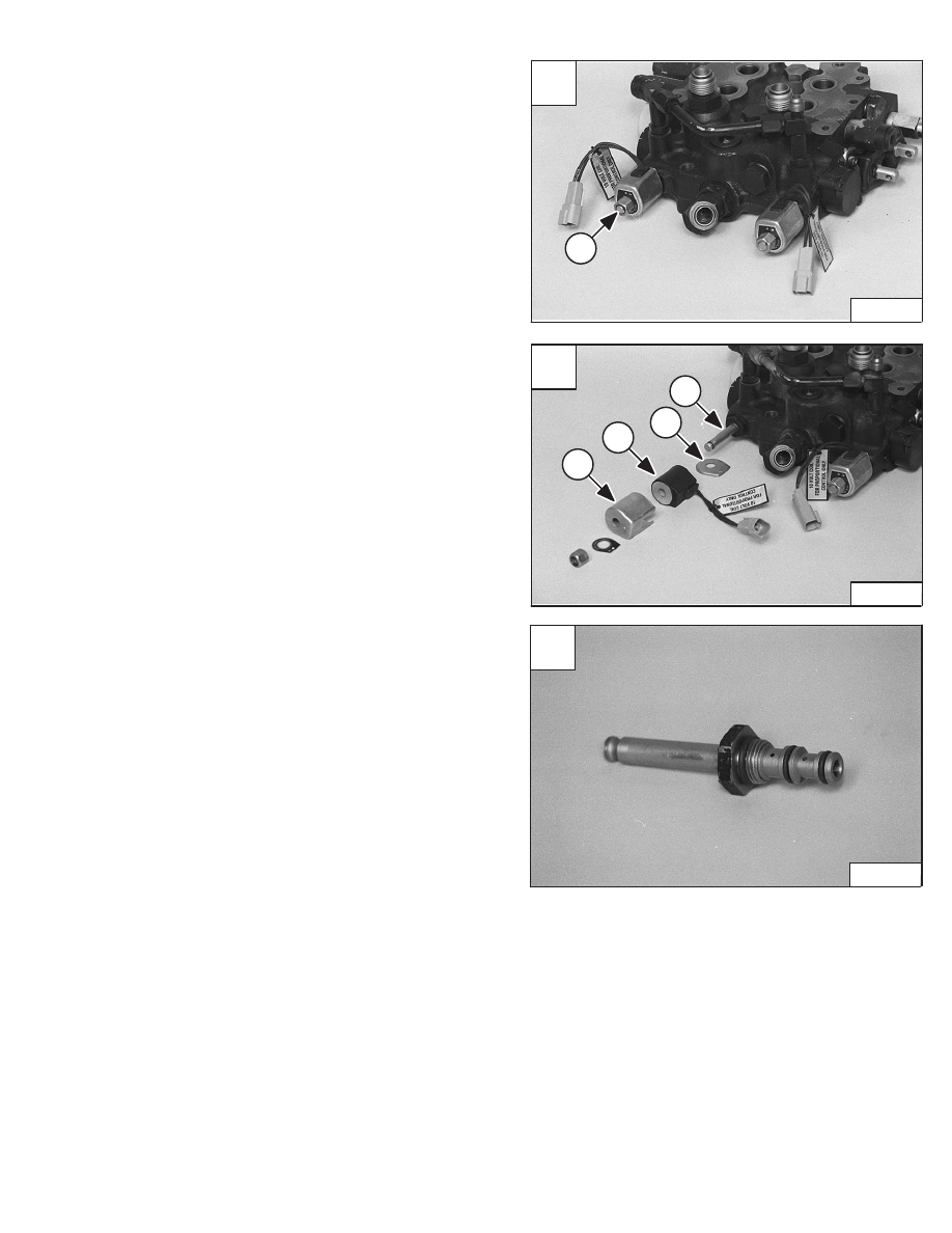
Auxiliary Electrical Solenoid
Remove the nut (Item 1) [A] from the end of the solenoid.
Installation: Tighten the nut to 9–12 in.–lbs. (1,02–1,36
Nm) torque.
Remove the metal housing (Item 1) [B], coil (Item 2) [B],
and end plate (Item 3) [B].
Remove the electric solenoid valve (Item 4) [B].
Installation: Tighten the solenoid valve to 96–144
in.–lbs. (10,8–16,3 Nm) torque.
Installation: Always install new O–rings and back–up
washers on the solenoid valve [C].
A
N–17265
1
C
N–17269
Service Manual
–10–61–
773 BICS Loader
Added June 01
B
N–17267
1
2
3
4
C
P–13746
HYDRAULIC CONTROL VALVE (Cont’d)
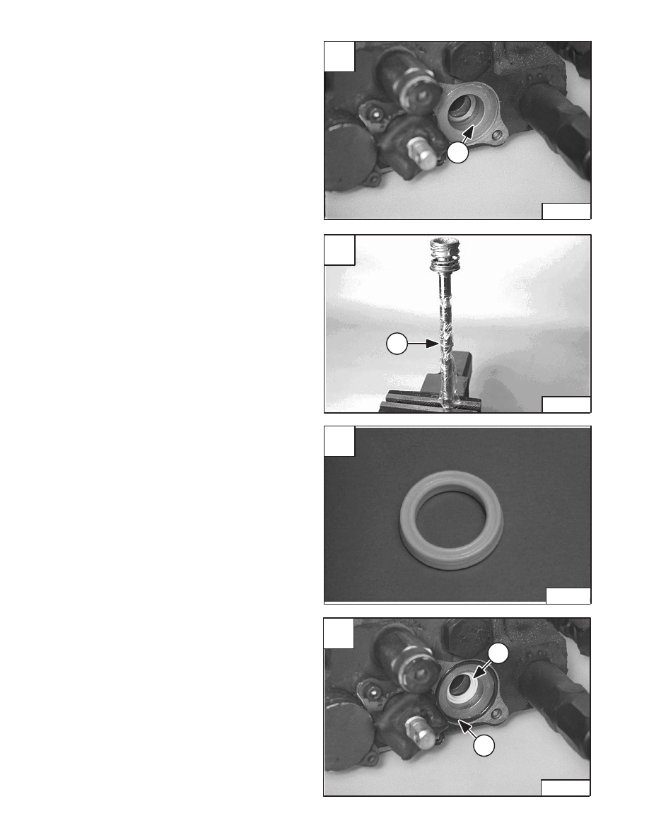
Spool Seal Installation
To install new spool seals when the centering spring is not
removed from the spool, use the following procedure:
Check the seal surface area in the control valve (Item 1)
[A] for rust, corrosion, scratches, etc. Correct any
irregularities before continuing.
Put plastic material (Example: Plastic food wrap) on the
valve spool [B].
Put clean oil on the spool seal. Install the spool seal (Item
1) [B] on the spool. Be careful not to damage the seal on
the sharp edges.
Remove the plastic material.
Install the spool into the control valve.
Install the linkage end spool seal [C] into the control valve
(Item 1) [D].
Be careful not to damage the spool seal.
Install the O–ring (Item 2) [D].
Continue assembling the control valve.
NOTE: Seal must be installed with lip face toward
valve body. Lift face has largest outside
diameter.
A
N–17491
1
D
N–17492
1
2
–10–62–
Service Manual
773 BICS Loader
Added June 01
B
CD–15080
1
HYDRAULIC CONTROL VALVE (Cont’d)
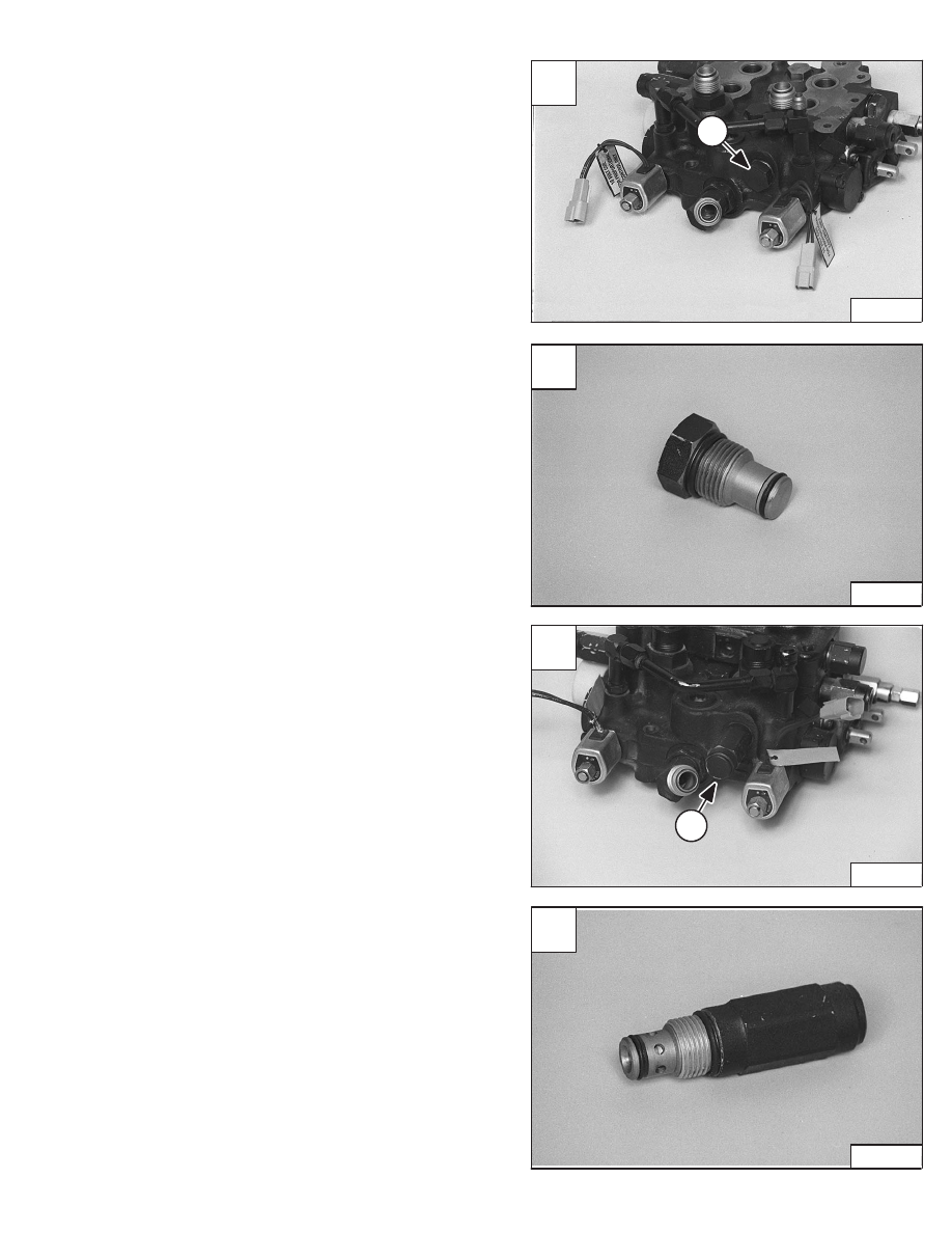
H–Port Auxiliary Section
Loosen the plug (Item 1) [A].
Installation: Tighten the plug to 35–40 ft.–lbs. (47–54
Nm) torque.
Remove the plug from the control valve [B].
Depending on the application of the auxiliaries, the control
valve may be equipped with a port relief valve (Item 1) [C].
If so equipped, remove the port relief from the control
valve [D].
Installation: Replace the O–rings and back–up washers.
Tighten the port relief valve 35–40 ft.–lbs. (47–54 Nm)
torque.
A
N–17265
1
D
N–17284
C
N–17474
1
Service Manual
–10–63–
773 BICS Loader
Added June 01
B
N–17266
Нет комментариевНе стесняйтесь поделиться с нами вашим ценным мнением.
Текст