Loader Bobcat 773. Manual — part 29
CONTROL VALVE (S/N 509640659 & Below, S/N
509616541 & Below) (Cont’d)
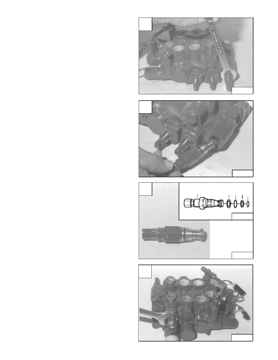
Main Relief Valve
Loosen the main relief valve [A].
Assemble: Always use new O–rings and back–up
washers. Tighten to 35–40 ft.–lbs. (47–54 Nm) torque.
Remove the main relief valve [B].
Remove the O–ring and back–up washers from the main
relief valve [C].
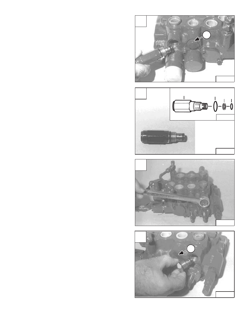
Port Relief Valve
Loosen the port relief valve [D].
Assemble: Always use new O–rings and back–up
washers. Tighten to 35–40 ft.–lbs. (47–54 Nm) torque.
NOTE: The port relief valve can be located on either
side of the control valve (E or F ports). (See
CONTROL VALVE Identification Chart Page
2–60.)
Revised Jan. 99
A
CD–10796
C
CD–10798
E–01509
1. Relief Valve
2. Back–up Washer
3. O–ring
4. O–ring
5. Back–up Washer
1
2 3 4 5
D
CD–10799
–2–62–
773 BICS Loader
Service Manual
B
CD–10797
CONTROL VALVE (S/N 509640659 & Below, S/N
509616541 & Below) (Cont’d)
Port Relief Valve (Cont’d)
Remove the port relief valve [A].
Remove the O–rings and back–up washer from the port
relief valve [B].
NOTE: The port (Item 1) [A] may contain an available
3500 PSI anti–cavitation/port relief valve for
the base end of the tilt section.
NOTE: The anti–cavitation valve can be located on
either side of the control valve (E or F ports).
(See CONTROL VALVE Identification Chart
Page 2–60.)
Remove the anti–cavitation valve from the control valve
[D].
NOTE: This port (Item 1) [D] may contain an available
3500 PSI port relief valve for the rod end of the
tilt section.
Anti–Cavitation Valve
Loosen the anti–cavitation valve [C].
Assemble: Always use new O–rings and back–up
washers. Tighten to 35–40 ft.–lbs. (47–54 Nm) torque.
Revised Jan. 99
A
CD–10800
1
C
CD–10802
D
CD–10803
1
773 BICS Loader
–2–63–
Service Manual
B
CD–10801
E–01509
1. Relief Valve
2. O–ring
3. Back–up Washer
4. O–ring
1
2
3
4

CONTROL VALVE (S/N 509640659 & Below, S/N
509616541 & Below) (Cont’d)
Anti–Cavitation Valve (Cont’d)
Remove the O–rings and back–up washer from the
anti–cavitation valve [A].
Rubber Boot
Loosen the two bolts on the rubber boot retainer [B].
Assemble: Tighten the bolts to 90–100 in.–lbs.
(10,2–11,3 Nm) torque.
Remove the bolts [C].
Remove the rubber boot and retainer [D].
Revised Jan. 99
A
CD–10804
E–01509
1. Anti–Cavitation Valve
2. O–ring
3. Back–up Washer
4. O–ring
1
2
3
4
C
CD–10806
D
CD–10807
–2–64–
773 BICS Loader
Service Manual
B
CD–10805

CONTROL VALVE (S/N 509640659 & Below, S/N
509616541 & Below) (Cont’d)
Rubber Boot (Cont’d)
Remove the back–up washer [A].
After the spool is removed, use a O–ring pick and remove
the spool seal from the spool bore [B].
NOTE: See Page 2–73 for spool seal identification
and installation.
Lift Spool Detent
The tool listed will be needed to do the following
procedure:
MEL1278 – Detent Tool
Remove the snap ring with a screwdriver [C].
Remove the snap ring and washer [D].
Revised Jan. 99
A
CD–10808
C
CD–10810
D
CD–10811
773 BICS Loader
–2–65–
Service Manual
B
CD–10809
Нет комментариевНе стесняйтесь поделиться с нами вашим ценным мнением.
Текст