Loader Bobcat 773. Manual — part 28

D
P–04097
1
2
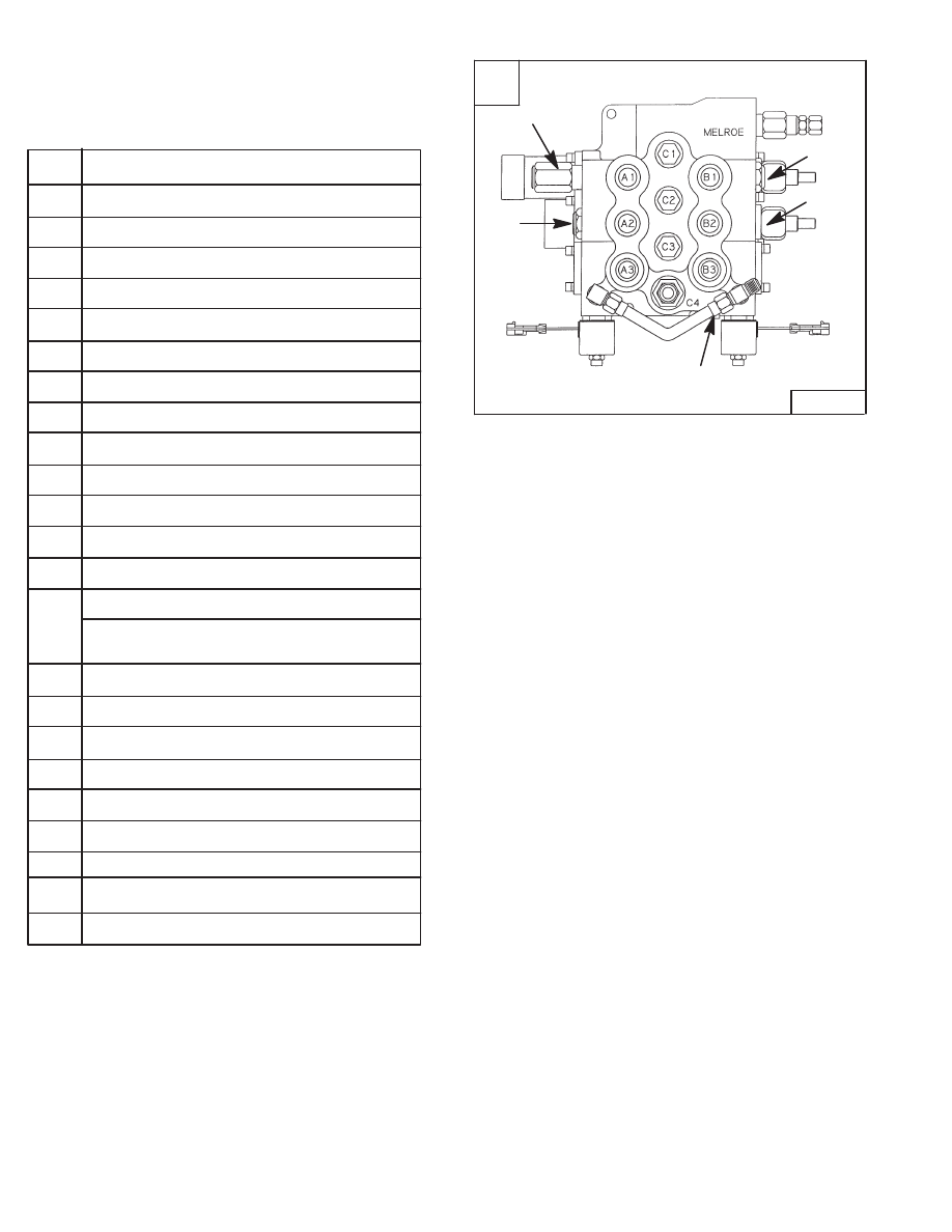
CONTROL VALVE (S/N 509460659 & Below, S/N
509616541 & Below) (Cont’d)
Removal And Installation (Cont’d)
Disconnect the tubeline (Item 1) [A] from the rear port of
the tilt section of the control valve.
Disconnect the tubeline (Item 2) [A] from the rear port of
the lift section of the control valve.
Disconnect the tubeline (Item 1) [B] from the front port of
the tilt section of the control valve.
Disconnect the tubeline (Item 2) [C] from the front port of
the lift section of the control valve.
Remove the clevis pin (Item 1) [D] from the tilt spool
linkage.
Remove the clevis pin (Item 2) [D] from the lift spool
linkage.
NOTE: The lift lock valve has been removed for
clarity purpose only.
A
P–04102
1
2
C
P–04111
1
–2–58–
773 BICS Loader
Service Manual
B
P–04107
1

CONTROL VALVE (S/N 509640659 & Below, S/N
509616541 & Below) (Cont’d)
Removal And Installation (Cont’d)
Remove the right rear tire.
Locate the rectangular access cover (Item 1) [A] on the
right side of the loader frame.
Loosen one mounting bolt and remove the other
mounting bolt from the access cover [B].
Rotate the cover to expose the access slot in the loader
[B].
Disconnect the inlet hose from the control valve through
the access slot [C].
Remove the two control valve mounting bolts & nuts.
Remove the control valve from the loader.
Installation: Tighten the mounting bolt & nut to 18–20
ft.–lbs. (24–27 Nm) torque.
Reverse the removal procedure to install the control
valve.
A
P–04109
1
C
P–04110
773 BICS Loader
–2–59–
Service Manual
B
P–04108
A1
Lift Cylinder Base End Restrictor
A2
Tilt Cylinder Base End
A3
Auxiliary Hydraulics
B1
Lift Cylinder Rod End
B2
Tilt Cylinder Rod End
B3
Auxiliary Hydraulics
C1
Load Check Valve/Lift Function
C2
Load Check Valve/Tilt Function
C3
Plug/Auxiliary Function
D1
Lift Spool Detent
D2
Centering Spring Tilt Spool
D3
Auxiliary Spool
E1
Port Relief
E2
Anti–Cav. Valve
Port Relief/Anti–cavitation Valve
(If Equipped)
F1
Anti–Cav. Valve
F2
Port Relief (If Equipped)
G1
Lift Spool
G2
Tilt Spool
G3
Auxiliary Spool
H1
Auxiliary Electric Solenoid
H2
Plug or Port Relief (Optional)
H3
Auxiliary Electric Solenoid
MR
Main Relief Valve
CONTROL VALVE (S/N 509640659 & Below, S/N
509616541 & Below) (Cont’d)
Identification Chart
Item
773 Series
Revised Jan. 99
A
MC–01423
MR
G1
G2
G3
H3
H1
D2
D3
D1
E1
H2
E2
F1
773 SERIES
F2
–2–60–
773 BICS Loader
Service Manual
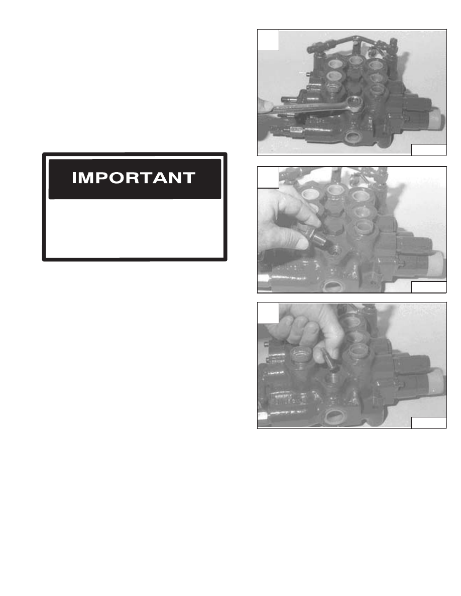
CONTROL VALVE (S/N 509640659 & Below, S/N
509616541& Below) (Cont’d)
Disassembly And Assembly
The anti–cavitation valve, port relief valves and plugs are
at different locations in the control valve. (Refer to Page
2–62 CONTROL VALVE Identification Chart for the
correct location of the parts for each Model control valve.)
NOTE: THE PHOTO’S MAY NOT SHOW THE EXACT
LOCATION FOR THE PART BEING
REMOVED OR INSTALLED ON THE
CONTROL VALVE, BUT THE PROCEDURE IS
THE SAME.
Mark each valve section and spool so that the parts will
be returned to its original bore during assemble.
Use bolts to fasten the control valve to a work bench for
easier disassemble and assemble.
Load Check Valve
Loosen the load check plug (C port).[A]. (See CONTROL
VALVE Identification Chart, Page 2–60.)
Assemble: Always use new O–ring. Tighten the plug to
35–40 ft.–lbs. (47–54 Nm) torque.
Remove the load check plug [B].
Remove the spring and poppet [C].
When repairing hydrostatic and hydraulic
systems, clean the work area before
disassembly and keep all parts clean. Always
use caps and plugs on hoses, tubelines and
ports to keep dirt out. Dirt can quickly damage
the system.
I–2003–0888
Revised Jan. 99
A
CD–10793
C
CD–10795
773 BICS Loader
–2–61–
Service Manual
B
CD–10794
Нет комментариевНе стесняйтесь поделиться с нами вашим ценным мнением.
Текст