Loader Bobcat 773. Manual — part 31
CONTROL VALVE (S/N 509640659 & Below, S/N
509616541 & Below) (Cont’d)
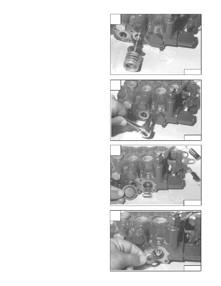
Tilt Centering Spring (Cont’d)
Remove the spool, centering spring, back–up washer and
spool seal [A].
Assemble: If the centering spring bolt is removed, tighten
to 90–100 in.–lbs. (10,2–11,3 Nm) torque. Put grease on
all the centering spring component parts. Always use new
spool seal.
Auxiliary Spool
Remove the end plate bolt [B].
Assemble: Tighten the bolt to 90–100 in.–lbs. (10,2–11,3
Nm) torque.
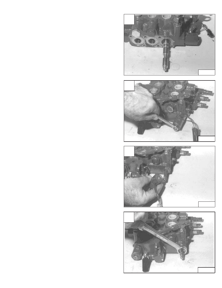
Remove the end plate, O–ring and spring [C].
Remove the end plate, O–ring and spring from the other
side.
Remove the washer (both sides) [D].
Revised Jan. 99
A
CD–10827
C
CD–10829
D
CD–10830
–2–70–
773 BICS Loader
Service Manual
B
CD–10828
CONTROL VALVE (S/N 509640659 & Below, S/N
509616541 & Below) (Cont’d)
Auxiliary Spool (Cont’d)
Remove the auxiliary section spool from the control valve
[A].
Auxiliary Electric Solenoid
Remove the nut from the end of the solenoid [B].
Assemble: Tighten the nut to 9–12 in.–lbs. (1,02–1,36
Nm) torque.
Remove the solenoid coil and end plate [C].
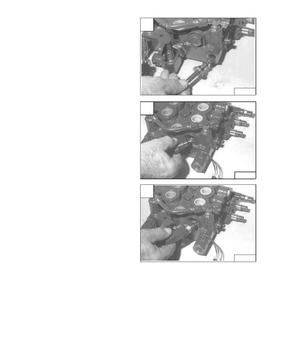
Loosen the electric solenoid valve [D].
Assemble: Tighten the electric solenoid valve to 96–144
in.–lbs. (10,8–16 Nm) torque.
Revised Jan. 99
A
CD–10831
C
CD–10833
D
CD–10834
773 BICS Loader
–2–71–
Service Manual
B
CD–10832
CONTROL VALVE (S/N 509640659 & Below, S/N
509616541 & Below) (Cont’d)
Auxiliary Electric Solenoid (Cont’d)
Remove the electric solenoid valve from the control valve
[A].
NOTE: Always use new O–rings and back–up
washers when assembling.
Remove the plug from the control valve (H port) [B]. (See
CONTROL VALVE Identification Chart, Page 2–60.)
Replace the O–ring.
Depending on the application of the auxiliaries, the control
valve may be equipped with a port relief valve (H port,)
[C]. (See CONTROL VALVE Identification Chart, Page
2–60.)
Remove the port relief valve and replace the O–rings and
back–up washers. (See Page 2–62.)
Inspection
Check the spools for wear or scratches.
Check that the spools are not loose in their bore.
Check that the centering springs are not broken.
Check that the load check valve seats are not worn.
Check the load check poppets for damage.
Check the rubber boots and retainers that they are not
worn or damaged.
Replace the parts as needed.
Revised Jan. 99
A
CD–10835
C
CD–10837
–2–72–
773 BICS Loader
Service Manual
B
CD–10836
CONTROL VALVE (S/N 509640659 & Below, S/N
509616541 & Below) (Cont’d)
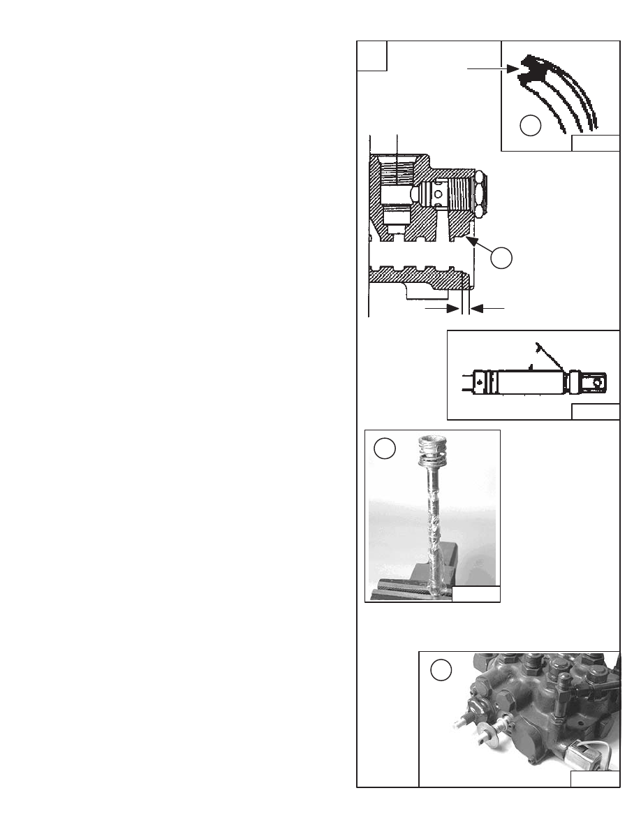
Identification And Installation Of Spool Seal
1. Uses only lip seal.
2. Check the seal surface area for rust, corrosion,
scratches, etc. Correct any irregularities before
continuing.
NOTE: Lubricate with grease between the seal and
retainer before installation (both ends).
3. Put clean oil on the valve spool. Install the lip seal
over the valve spool. Be Careful not to damage the
lip seal on the valve spool edges.
NOTE: An alternate method is to protect the lip seal
by putting plastic material (Example:
Discarded microfiche card) over the spool to
protect the seal.
4. Install spool into the valve bore.
5. Slide the linkage end lip seal over the rubber boot
groove. Be Careful not to damage the seal.
6. Install the seal retainer.
7. Continue with assembling the control valve.
Revised Jan. 99
A
CD–15081
MC–01699
LATEST PRODUCTION
MC–01606
1
CUT AWAY SIDE VIEW
OF VALVE BODY
0.145’’ (3,7 mm)
CD–15080
INSTALLING LIP
INSTALLING LIP SEAL
RETAINER
6
2
LIP FACE
TOWARD
VALVE BODY
45
°
SEAL ON VALVE
SPOOL
3
773 BICS Loader
–2–73–
Service Manual
Нет комментариевНе стесняйтесь поделиться с нами вашим ценным мнением.
Текст