Loader Bobcat 773. Manual — part 105
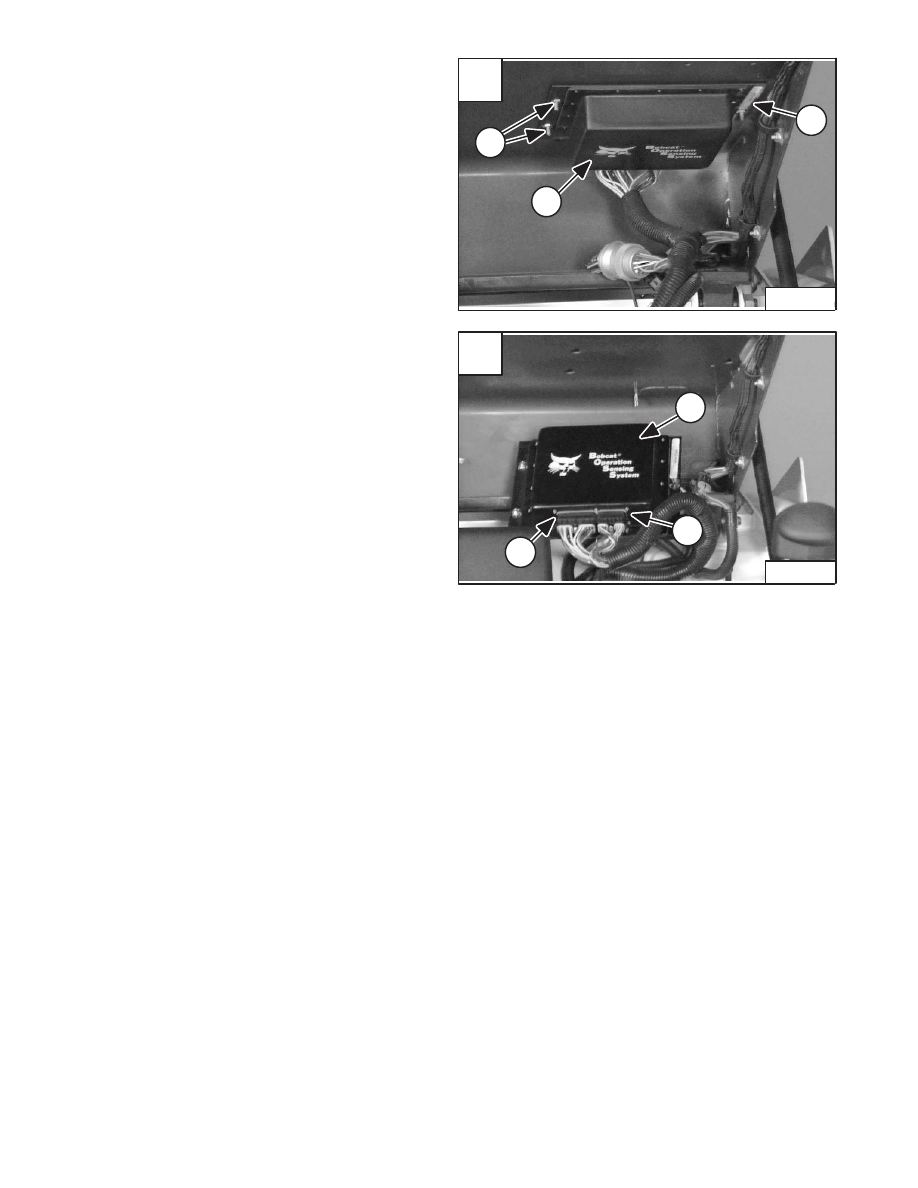
OPERATION SENSING SYSTEM UNIT
Removal And Installation
Raise the loader operator cab. (See Page 1–1.)
Loosen the three nuts (Item 1) [A] from the sensing
system unit (Item 2) [A].
Slide the unit forward in the mounting slots and remove
it from the operator cab.
Use a screw driver and remove the two connectors (Item
1) [B] from the sensing system unit (Item 2) [B].
Installation: Put the heads of the mounting bolts into the
slots of the operator cab and slide the unit back into place.
Tighten the three mounting nuts to 80–90 in.–lbs. (9–10
Nm) torque.
Revised Jan. 99
A
P–04043
1
2
1
–8–26–
773 BICS Loader
Service Manual
B
P–04042
2
1
1
BOSS
®
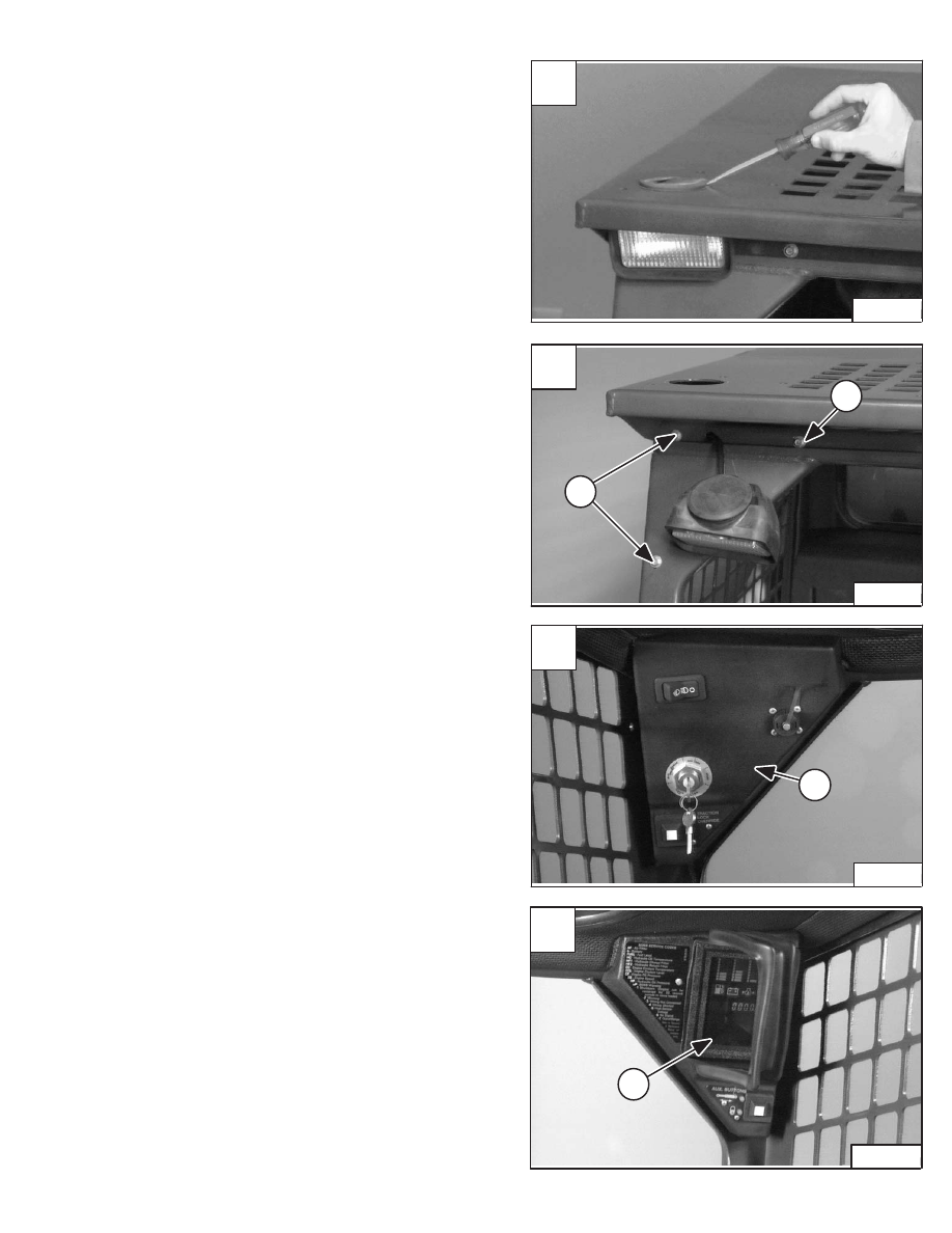
INSTRUMENT PANEL
Removal And Installation
Pry the rubber light mount free from the operator cab
(both sides) [A].
Lower the light from the operator cab to locate the three
instrument panel mounting bolts (Item 1) [B] (both sides).
Remove the three mounting bolts and pull the left panel
(Item 1) [C] down from the operator cab.
Installation: Be careful to not overtighten the panel
mounting bolts to prevent stripping the threaded holes of
the panels.
Disconnect the wire harness connectors from the panel
and remove the panel.
Remove the three mounting bolts and pull the right panel
(Item 1) [D] down from the operator cab.
Installation: Be careful to not overtighten the panel
mounting bolts to prevent stripping the threaded holes of
the panels.
Disconnect the wire harness connectors from the panel
and remove the panel.
Revised Jan. 99
A
P–03995
C
P–03958
1
D
P–03959
1
773 BICS Loader
–8–27–
Service Manual
B
P–03955
1
1
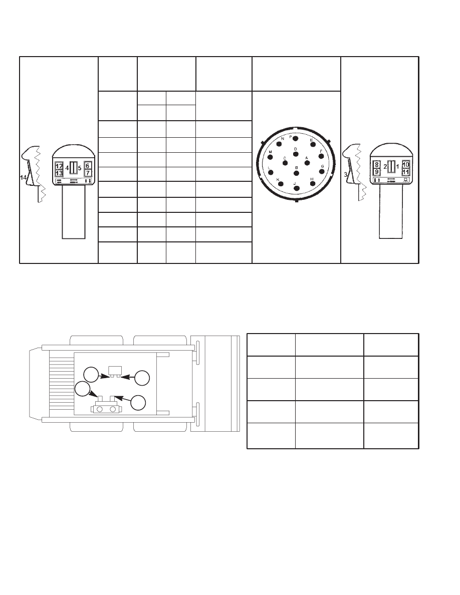
ELECTRICAL/HYDRAULIC CONTROLS REFERENCE
Controls Identification Chart
Left Side
Control Handle
Switches
Switch
Number
1
2
3
4
5
6
7
8
9
10, 11, 12,
13, 14
Attachment
Harness
Terminal
Activated
K
K
K
K, A, D
K, A, C
K, E
K, F
K, G
K, H
K
Attachment
Harness
Connector
Right Side
Control Handle
Switches
Solenoid
Number
Activated
RH
1
1
2
2
1
1
2
2,3
1
1,3
1
1,3
1
1,3
1
1,3
1
1,3
–
––
Viewed from front
(pin side of connector)
of loader.
Solenoid
Number
Hydraulic
Coupler
Wiring
Color
1
2
3
4
Front
Female
Front
Male
Diverter
(Rear Couplers)
Bleed – Rear
Male & Female
Dk. Green/
Red
Dk. Green/
Lt. Green
Yellow
Dk. Green/
Yellow
NOTE: To relieve the hydraulic pressure trapped in the front auxiliary circuit, with the engine running, turn the
key switch quickly to the left (counterclockwise) past the OFF position. Hold key until the engine comes
to a complete stop.
7
7
3
TS–01494
RH – Loaders with Rear Hydraulics Option.
HFH – Loaders with High Flow Hydraulics Option.
* If harness terminals K & L are jumped together, switches 4 thru 9 provide flow on demand to female coupler.
(DETENT is not needed.)
* Terminal K is activated with Key switch ON.
*
4
3
2
1
–8–28–
773 BICS Loader
Service Manual
773 Service Manual #6900092–Systems Analysis Section Part 2 of 2
SPECIFICATIONS
773 BICS Loader
–9–1–
Service Manual
SPECIFICATIONS
DECIMAL AND MILLIMETER EQUIVALENTS
Chart
9–17
. . . . . . . . . . . . . . . . . . . . . . . . . . . . . . . . . . . . . . . . . . . . . . . . . . . . . . . .
ENGINE SPECIFICATIONS
Camshaft
9–6
. . . . . . . . . . . . . . . . . . . . . . . . . . . . . . . . . . . . . . . . . . . . . . . . . . . .
Connecting Rod
9–6
. . . . . . . . . . . . . . . . . . . . . . . . . . . . . . . . . . . . . . . . . . . . . . .
Crankshaft
9–7
. . . . . . . . . . . . . . . . . . . . . . . . . . . . . . . . . . . . . . . . . . . . . . . . . . .
Crankshaft Re–Grind Data
9–8
. . . . . . . . . . . . . . . . . . . . . . . . . . . . . . . . . . . . .
Cylinders
9–6
. . . . . . . . . . . . . . . . . . . . . . . . . . . . . . . . . . . . . . . . . . . . . . . . . . . . .
Cylinder Head
9–5
. . . . . . . . . . . . . . . . . . . . . . . . . . . . . . . . . . . . . . . . . . . . . . . .
Fuel Injector Nozzle
9–5
. . . . . . . . . . . . . . . . . . . . . . . . . . . . . . . . . . . . . . . . . . .
Fuel Injection Pump
9–5
. . . . . . . . . . . . . . . . . . . . . . . . . . . . . . . . . . . . . . . . . . .
Oil Pump
9–6
. . . . . . . . . . . . . . . . . . . . . . . . . . . . . . . . . . . . . . . . . . . . . . . . . . . . .
Pistons
9–6
. . . . . . . . . . . . . . . . . . . . . . . . . . . . . . . . . . . . . . . . . . . . . . . . . . . . . .
Piston Rings
9–6
. . . . . . . . . . . . . . . . . . . . . . . . . . . . . . . . . . . . . . . . . . . . . . . . . .
Rocker Arms
9–5
. . . . . . . . . . . . . . . . . . . . . . . . . . . . . . . . . . . . . . . . . . . . . . . . .
Tappet
9–6
. . . . . . . . . . . . . . . . . . . . . . . . . . . . . . . . . . . . . . . . . . . . . . . . . . . . . . .
Thermostat
9–7
. . . . . . . . . . . . . . . . . . . . . . . . . . . . . . . . . . . . . . . . . . . . . . . . . . .
Timing Gear
9–7
. . . . . . . . . . . . . . . . . . . . . . . . . . . . . . . . . . . . . . . . . . . . . . . . . .
Torque for General Metric Bolts
9–9
. . . . . . . . . . . . . . . . . . . . . . . . . . . . . . . . .
Valves
9–5
. . . . . . . . . . . . . . . . . . . . . . . . . . . . . . . . . . . . . . . . . . . . . . . . . . . . . . .
Valve Springs
9–5
. . . . . . . . . . . . . . . . . . . . . . . . . . . . . . . . . . . . . . . . . . . . . . . . .
Valve Timing
9–5
. . . . . . . . . . . . . . . . . . . . . . . . . . . . . . . . . . . . . . . . . . . . . . . . . .
HYDRAULIC/HYDROSTATIC FLUID SPECIFICATIONS
Specifications
9–17
. . . . . . . . . . . . . . . . . . . . . . . . . . . . . . . . . . . . . . . . . . . . . . . . .
HYDRAULIC CONNECTION SPECIFICATIONS
Flare Fitting
9–10
. . . . . . . . . . . . . . . . . . . . . . . . . . . . . . . . . . . . . . . . . . . . . . . . . .
O–Ring Face Seal Connection
9–10
. . . . . . . . . . . . . . . . . . . . . . . . . . . . . . . . . .
O–Ring Flare Fitting
9–11
. . . . . . . . . . . . . . . . . . . . . . . . . . . . . . . . . . . . . . . . . . .
Port Seal Fitting
9–13
. . . . . . . . . . . . . . . . . . . . . . . . . . . . . . . . . . . . . . . . . . . . . . .
Straight Thread O–Ring Fitting
9–10
. . . . . . . . . . . . . . . . . . . . . . . . . . . . . . . . . .
Tubelines And Hoses
9–10
. . . . . . . . . . . . . . . . . . . . . . . . . . . . . . . . . . . . . . . . . .
LOADER SPECIFICATIONS
Capacities
9–4
. . . . . . . . . . . . . . . . . . . . . . . . . . . . . . . . . . . . . . . . . . . . . . . . . . . .
Controls
9–3
. . . . . . . . . . . . . . . . . . . . . . . . . . . . . . . . . . . . . . . . . . . . . . . . . . . . . .
Drive System
9–4
. . . . . . . . . . . . . . . . . . . . . . . . . . . . . . . . . . . . . . . . . . . . . . . . .
Electrical
9–4
. . . . . . . . . . . . . . . . . . . . . . . . . . . . . . . . . . . . . . . . . . . . . . . . . . . . .
Engine
9–3
. . . . . . . . . . . . . . . . . . . . . . . . . . . . . . . . . . . . . . . . . . . . . . . . . . . . . . .
Floor Pressure
9–4
. . . . . . . . . . . . . . . . . . . . . . . . . . . . . . . . . . . . . . . . . . . . . . . .
Hydraulic System
9–4
. . . . . . . . . . . . . . . . . . . . . . . . . . . . . . . . . . . . . . . . . . . . .
Specifications
9–3
. . . . . . . . . . . . . . . . . . . . . . . . . . . . . . . . . . . . . . . . . . . . . . . . .
Performance
9–3
. . . . . . . . . . . . . . . . . . . . . . . . . . . . . . . . . . . . . . . . . . . . . . . . .
Tires
9–4
. . . . . . . . . . . . . . . . . . . . . . . . . . . . . . . . . . . . . . . . . . . . . . . . . . . . . . . . .
STANDARD TORQUE SPECIFICATIONS FOR BOLTS
Chart
9–16
. . . . . . . . . . . . . . . . . . . . . . . . . . . . . . . . . . . . . . . . . . . . . . . . . . . . . . . .
TORQUE SPECIFICATIONS FOR LOADER
Specifications
9–15
. . . . . . . . . . . . . . . . . . . . . . . . . . . . . . . . . . . . . . . . . . . . . . . . .
U.S. TO METRIC CONVERSION
Chart
9–17
. . . . . . . . . . . . . . . . . . . . . . . . . . . . . . . . . . . . . . . . . . . . . . . . . . . . . . . .
Page
Number
Revised May 98
Нет комментариевНе стесняйтесь поделиться с нами вашим ценным мнением.
Текст