Loader Bobcat 773. Manual — part 54

PARKING BRAKE DISC
Removal And Installation
Raise the loader lift arms and install an approved lift arm
support device. (See Page 1–1.)
A snap ring pliers with 90
°
tips are necessary for removing
the parking brake disc.
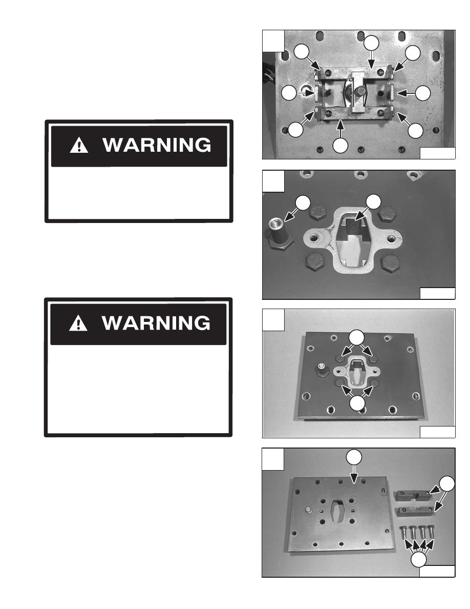
Use the snap ring pliers and remove the snap ring from
the end of the sprocket on the hydrostatic motor carrier
[B].
NOTE: Later machines use a snap ring on both sides
of each brake disc [B].
NOTE: Brake disc guides (Item 4) [A] are used only
on earlier machines.
Raise the loader operator cab. (See Page 1–1.)
Disconnect and remove the engine speed control. (See
Page 7–1.)
Remove the control panel from the loader. (See Page
3–1.)
Remove the center chaincase cover. (See Page 4–9.)
Remove the front chaincase cover. (See Page 4–10.)
Remove the traction lock assembly. (See Page 8–1.)
The parking brake discs (Item 1) [A] are located beneath
the center chaincase cover (Item 2) [A].
Inspect the traction lock guides (Item 3) [A] and the brake
disc guides (Item 4) [A] for damage or wear and replace
as necessary. (See Page 4–5.)
Revised May 98
Slide the brake disc (Item 1) [C] off the sprocket and
remove the brake disc through the front chaincase cover.
Reverse the removal procedure to install the parking
brake disc in the loader.
Refer to Page 8–1 for the traction lock inspection
procedure.
Never work on a machine with the lift arms up
unless the lift arms are secured by an approved
lift arm support device. Failure to use an
approved lift arm support device can allow the
lift arms or attachment to fall and cause injury
or death.
W–2059–0598
A
P–04137
2
4
4
1
1
3
3
B
P–04163
C
P–04166
1
–4–4–
773 BICS Loader
Service Manual
Raise the loader operator cab. (See Page 1–1.)
Disconnect and remove the engine speed control. (See
Page 7–1.)
Remove the control panel from the loader. (See Page
3–1.)
Remove the traction lock assembly. (See Page 8–1.)
Remove the center chaincase cover. (See Page 4–9.)
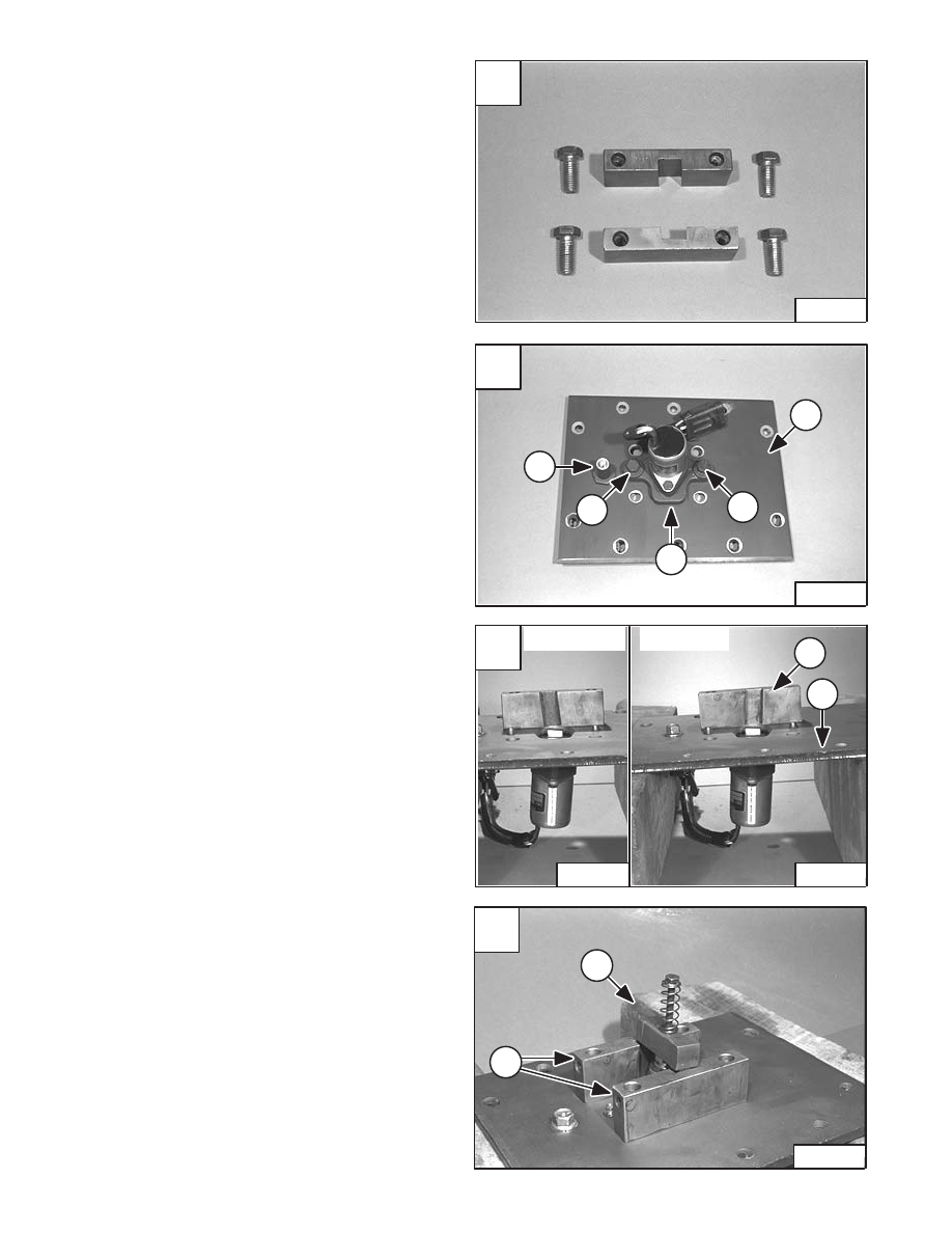
After the center chaincase cover is removed from the
machine locate the traction lock guides (Item 1) [A] & [B].
To remove the brake disc guides (Item 2) [A] remove the
four bolts (Item 3) [A] older models only.
NOTE: Bolt (Item 2) [B] is on the rear of the chaincase
cover, notice the direction of the groove (Item
1) [B] in the traction lock guides.
To remove the traction lock guides remove the four bolts
(Item 1) [C].
Thoroughly clean the polyurethane from the chaincase
cover (Item 1) [D], bolts (Item 2) [D] and traction lock
guides (Item 3) [D] and dry.
TRACTION LOCK GUIDES
The part number listed will be needed to do the following
procedure:
P/N 6633583 – Polyurethane
Disassembly
Raise the loader lift arms and install an approved lift arm
support device. (See Page 1–1.)
Revised June 01
Never work on a machine with the lift arms up
unless the lift arms are secured by an approved
lift arm support device. Failure to use an
approved lift arm support device can allow the
lift arms or attachment to fall and cause injury
or death.
W–2059–0598
Do not modify the electrical wiring connected
to the traction lock solenoid or any part of the
traction lock system. The traction lock
provides the locking function of the parking
brake. Service work on the traction lock system
should only be performed by a qualified
technician. Use only genuine Bobcat parts if
repair is necessary.
W–2165–0100
AVOID INJURY OR DEATH
A
P–11328
1
3
2
3
1
3
2
3
C
P–11330
1
1
D
P–11332
3
2
1
773 BICS Loader
–4–5–
Service Manual
B
P–11331
1
2
TRACTION LOCK GUIDES (Cont’d)
Assembly
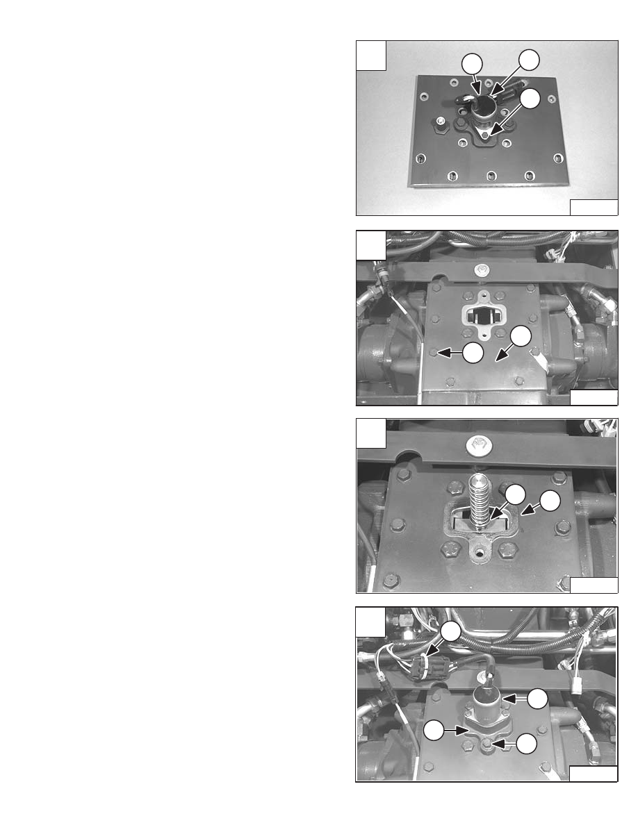
Apply a bead of polyurethane (P/N 6633583) on the
traction lock guides and bolts [A].
Install the electric solenoid/bracket assembly (Item 1) [B]
to the center chaincase cover (Item 2) [B].
NOTE: Bolt (Item 3) [B] & [C] represents the rear of
the chaincase cover.
Install and tighten the two bolts (Item 4) [B].
Install the traction lock guides (Item 1) [C] to the
chaincase cover (Item 2) [C] using the four bolts
(removed earlier).
Do not tighten at this time.
Install the traction wedge assembly (Item 1) [D] into the
solenoid and traction lock guides (Item 2) [D].
NOTE: The wedge assembly must slide freely in the
grooves of the guides. Tighten the four guide
bolts to 90–100 ft.–lbs. (123–135 Nm) torque.
After the bolts have been tightened recheck to make sure
the shaft assembly is moving freely in the guides.
Remove the wedge assembly (Item 1) [D].
A
P–11333
C
P–11335
P–11336
1
2
INCORRECT
CORRECT
D
P–11337
1
2
–4–6–
773 BICS Loader
Service Manual
B
P–11334
2
3
4
1
4
TRACTION LOCK GUIDES (Cont’d)
Assembly (Cont’d)
Remove the two bolts (Item 1) [A] and remove the electric
solenoid (Item 2) [A] from the center chaincase cover.
Install the chaincase cover (Item 1) [B] using the ten
mounting bolts (Item 2) [B].
Tighten to 25–28 ft.–lbs. (34–38 Nm) torque.
NOTE: Thoroughly clean and dry the bolts and apply
LOCTITE #242.
Install the wedge assembly (Item 1) [C] into the grooves
in the traction lock guides making sure that there is no
binding.
Install the gasket (Item 2) [C].
Install the solenoid mounting bracket assembly (Item 1)
[D] on the chaincase cover using the two bolts (Item 2) [D]
and tighten to 25–28 ft.–lbs. (34–38 Nm) torque.
NOTE: Be sure the solenoid mounting bracket is
installed in the same position. The solenoid
mounting surface has a slight angle which
tips the top of the solenoid toward the rear of
the loader when installed correctly.
Install a new DO NOT MODIFY sta–strap (Item 3) [D]
(P/N 6665527) on the electric solenoid connector.
Install the control panel. (See Page 3–1.)
Install the engine speed control. (See Page 7–1.)
Lower operator cab. (See Page 1–1.)
Perform the BICS
™
inspection procedure. (See Page
8–1.)
A
P–11334
2
1
1
C
P–11340
1
2
D
P–11341
3
2
2
1
773 BICS Loader
–4–7–
Service Manual
B
P–11339
1
2
Нет комментариевНе стесняйтесь поделиться с нами вашим ценным мнением.
Текст