Loader Bobcat 773. Manual — part 53
FIXED DRIVE BELT TENSIONER PULLEY (Cont’d)
Assembly (Cont’d)
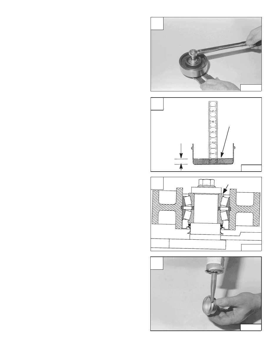
Tighten the bolt to 25–28 ft.–lbs. (43–38 Nm) torque [A].
Use only 15W/50 synthetic oil (example: Mobil One) for
the bearings. Use the cap and add oil until it is at the 0.500
inch (12,7 mm) mark on the scale, which should be 0.75
oz. (20 C.C.) of oil [B].
Add the oil slowly, at one location of the bearing which will
allow the trapped air to escape from the other side [C].
Check the cap sealing edge to make sure it is not
damaged. Replace the cap as needed.
Make sure the sealing edge on the hub bore and cap
sealing edge is clean and free of oil, put a bead of sealant
(P/N 6633538) on the cap [D].
Install the cap.
NOTE: Oil capacity is very critical, do not add any
more and/or any less oil to the idler pulley.
A
CD–12652
C
MC–01648
OIL LEVEL
D
CD–12653
773 BICS Loader
–3–65–
Service Manual
B
MC–01648
0.75 oz.
(20 C.C.)
Capacity
0.500’’ (12,7 mm)
Measure Oil
Level in the
Center of the Cap

C
N–00831
3
2
1
FIXED DRIVE BELT TENSIONER PULLEY (Cont’d)
Checking Pulley End Play
Install the pulley/mounting bracket assembly in to vise.
Install a dial indicator on the pulley hub [A].
Move the pulley by hand, back and forth. The correct end
play is 0.005–0.013 inch (0,13–0,33 mm) [B].
If the end play is not correct, there is no adjustment
replace the hub, pulley and/or bearings.
OIL COOLER
Removal and Installation
Open the rear door of the loader.
Raise the rear grill.
Disconnect the inlet and outlet hoses (Items 1 & 2) [C]
from the oil cooler (Item 3) [C].
Lift up the oil cooler and remove the cooler from the
loader.
Reverse the removal procedure to install the oil cooler.
When repairing hydrostatic and hydraulic
systems, clean the work area before
disassembly and keep all parts clean. Always
use caps and plugs on hoses, tubelines and
ports to keep dirt out. Dirt can quickly damage
the system.
I–2003–0888
A
CD–12655
–3–66–
773 BICS Loader
Service Manual
773 Service Manual #6900092–Hydrostatic System Section Part 3 of 3
B
CD–12656
DRIVE
SYSTEM
773 BICS Loader
–4–1–
Service Manual
DRIVE SYSTEM
AXLE SEAL
Removal And Installation
4–19
. . . . . . . . . . . . . . . . . . . . . . . . . . . . . . . . . . . . . . .
AXLE, SPROCKET AND BEARINGS
Removal And Installation
4–21
. . . . . . . . . . . . . . . . . . . . . . . . . . . . . . . . . . . . . . .
CHAINCASE COVERS
Center Chaincase Cover Removal And Installation
4–9
. . . . . . . . . . . . . . . .
Front Chaincase Cover Removal And Installation
4–10
. . . . . . . . . . . . . . . . . .
Rear Chaincase Cover Removal And Installation
4–10
. . . . . . . . . . . . . . . . . .
CHAINCASE FLUID
Removing Oil From The Chaincase
4–8
. . . . . . . . . . . . . . . . . . . . . . . . . . . . . .
DRIVE CHAIN
Removal And Installation
4–25
. . . . . . . . . . . . . . . . . . . . . . . . . . . . . . . . . . . . . . .
MOTOR CARRIER
Assembly
4–15
. . . . . . . . . . . . . . . . . . . . . . . . . . . . . . . . . . . . . . . . . . . . . . . . . . . .
Disassembly
4–14
. . . . . . . . . . . . . . . . . . . . . . . . . . . . . . . . . . . . . . . . . . . . . . . . . .
Removal And Installation
4–13
. . . . . . . . . . . . . . . . . . . . . . . . . . . . . . . . . . . . . . .
Shaft Seal Replacement
4–11
. . . . . . . . . . . . . . . . . . . . . . . . . . . . . . . . . . . . . . .
PARKING BRAKE
Disassembly And Assembly
4–3
. . . . . . . . . . . . . . . . . . . . . . . . . . . . . . . . . . . .
Removal And Installation
4–3
. . . . . . . . . . . . . . . . . . . . . . . . . . . . . . . . . . . . . . .
PARKING BRAKE DISC
Removal And Installation
4–4
. . . . . . . . . . . . . . . . . . . . . . . . . . . . . . . . . . . . . . .
TRACTION LOCK GUIDES
Assembly
4–6
. . . . . . . . . . . . . . . . . . . . . . . . . . . . . . . . . . . . . . . . . . . . . . . . . . . .
Disassembly
4–5
. . . . . . . . . . . . . . . . . . . . . . . . . . . . . . . . . . . . . . . . . . . . . . . . . .
TIGHTEN ALL HARDWARE PER SIZE TO GRADE 5 TORQUE (SEE
STANDARD TORQUE SPECIFICATIONS FOR BOLTS, SECTION 9)
UNLESS OTHERWISE SPECIFIED.
Page
Number
PARKING BRAKE
Removal And Installation
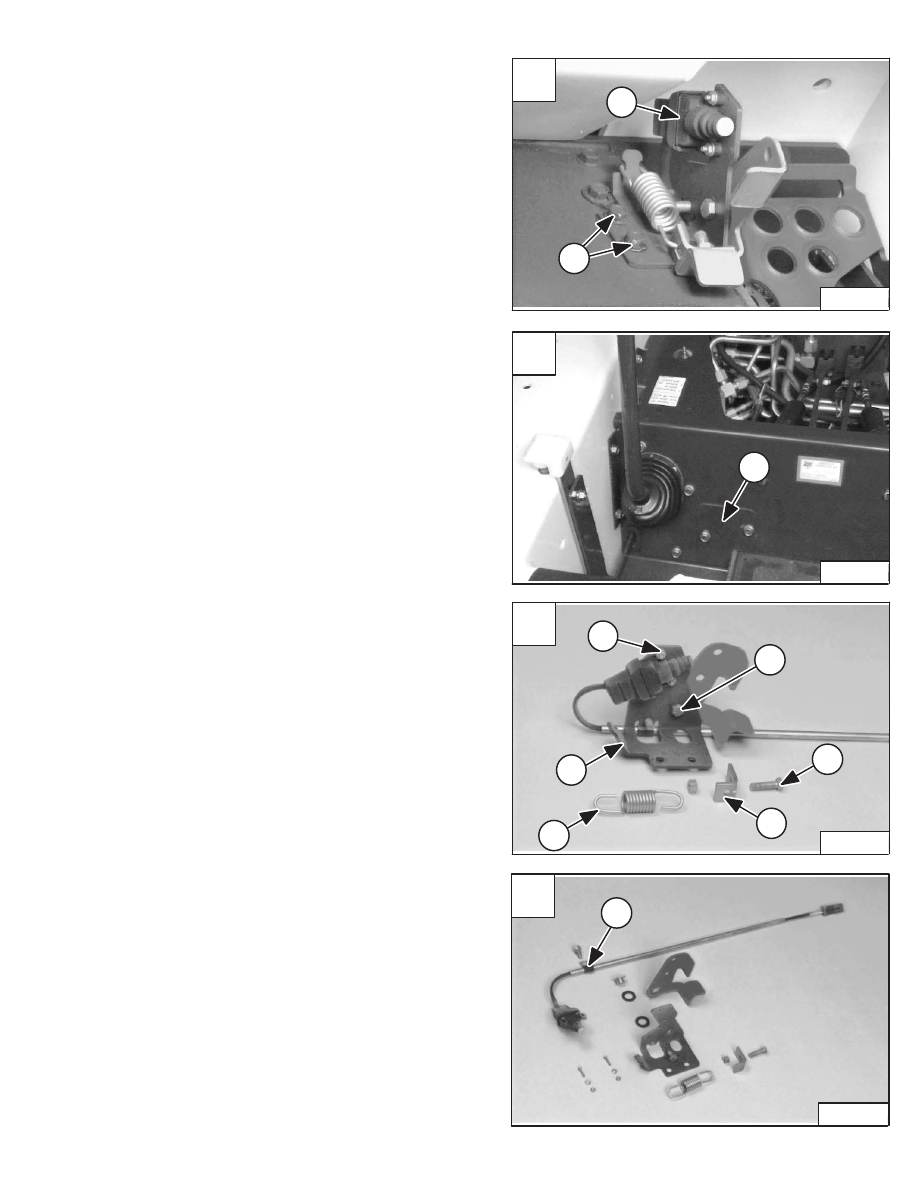
Raise the loader operator cab. (See Page 1–1.)
Remove the two mounting bolts (Item 1) [A] from the
brake pedal mounting bracket.
Installation: Tighten the mounting bolts to 25–28 ft.–lbs.
(34–38 Nm) torque.
Remove the cover (Item 1) [B] from the front of the control
panel.
Disconnect the electrical connector from the parking
brake pedal sensor (Item 2) [A]. The connector is located
behind the control panel.
Remove the parking brake assembly from the loader.
Reverse the removal procedure to install the parking
brake assembly in the loader.
Disassembly And Assembly
Loosen and remove the mounting bolt (Item 1) [C] and nut
from the spring mounting bracket (Item 2) [C].
Remove the brake pedal spring (Item 3) from the tension
spring mounting bracket (Item 2) [C] and from the brake
pedal mounting bracket (Item 4) [C].
Remove the two mounting bolts, washers and nuts (Item
5) [C] from the brake pedal sensor.
Remove the harness mounting clamp (Item 1) [D] from
the pedal mounting bracket (Item 4) [C].
Remove the sensor harness from the pedal mounting
bracket.
Remove the pedal mounting bolt (Item 6) [C], plastic
spacers and bushing nut from the brake pedal.
Remove the pedal from the pedal mounting bracket.
Photo [D] shows the parking brake disassembled to
identify the existing parts in the brake assembly.
C
P–04189
6
3
1
2
4
5
D
P–04156
1
A
P–03989
2
1
773 BICS Loader
–4–3–
Service Manual
B
P–04073
1
Нет комментариевНе стесняйтесь поделиться с нами вашим ценным мнением.
Текст